


Pelco Manual C550M-E (8/97) 7
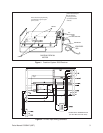
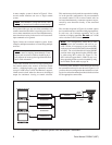
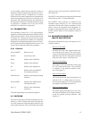
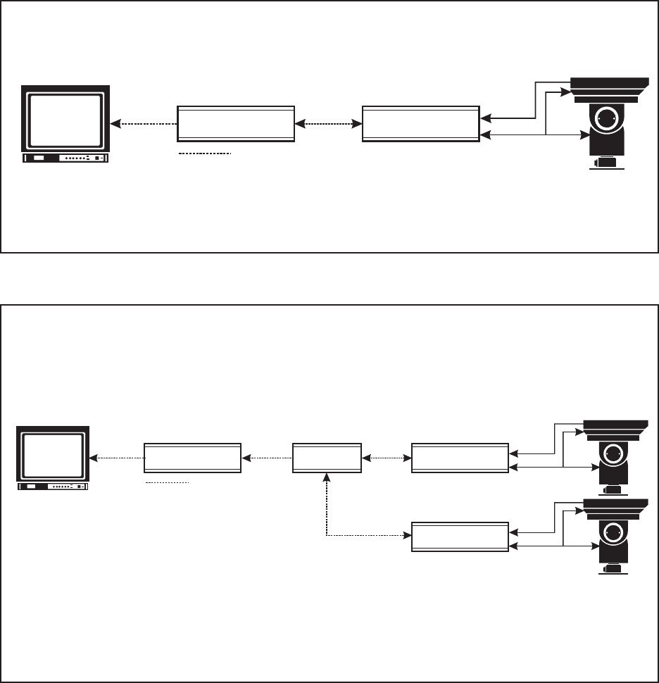
Figure 7. Coaxitron System 2000 with Manual Video Switcher and Multiple Cameras
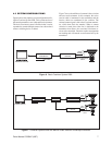
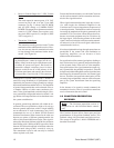
Figure 6. Basic Coaxitron System 2000
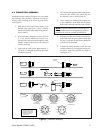
4.3 SYSTEM CONFIGURATIONS
Figure 6 shows the simplest system configuration utiliz-
ing the Coaxitron System 2000. This system consists of
the control transmitter, coax cable and receiver/camera.
This basic Coaxitron system is flexible in that it can be
expanded to control multiple camera sites when a hard
contact switching device is added.
Figure 7 shows the addition of a manual video switcher
and one receiver/camera. In this example, the active
coaxial cable is terminated in the transmitter and the
inactive cables are terminated in the switcher. The
selected camera signal is fed to the Coaxitron transmit-
ter, which then feeds the monitor. When a camera
selection is made, that video line is dedicated to the
transmitter that allows the associated Coaxitron re-
ceiver to be controlled. Functions such as auto/random
are latching and will remain on until turned off by the
transmitter.
COAXITRON
TRANSMITTER
COAXITRON
RECEIVER
COAXITRON
VIDEO
SIGNAL
MULTI-CONDUCTOR
CABLE
TERMINATE MONITOR
COAXITRON
TRANSMITTER
COAXITRON
RECEIVER
COAXITRON
VIDEO
SIGNAL
MULTI-CONDUCTOR
CABLE
COAXITRON
RECEIVER
VIDEO
SIGNAL
MULTI-CONDUCTOR
CABLE
MANUAL
SWITCHER
TERMINATE MONITOR