


Pelco Manual C550M-E (8/97) 21
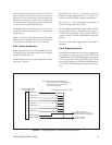
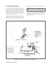
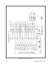
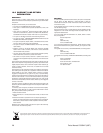
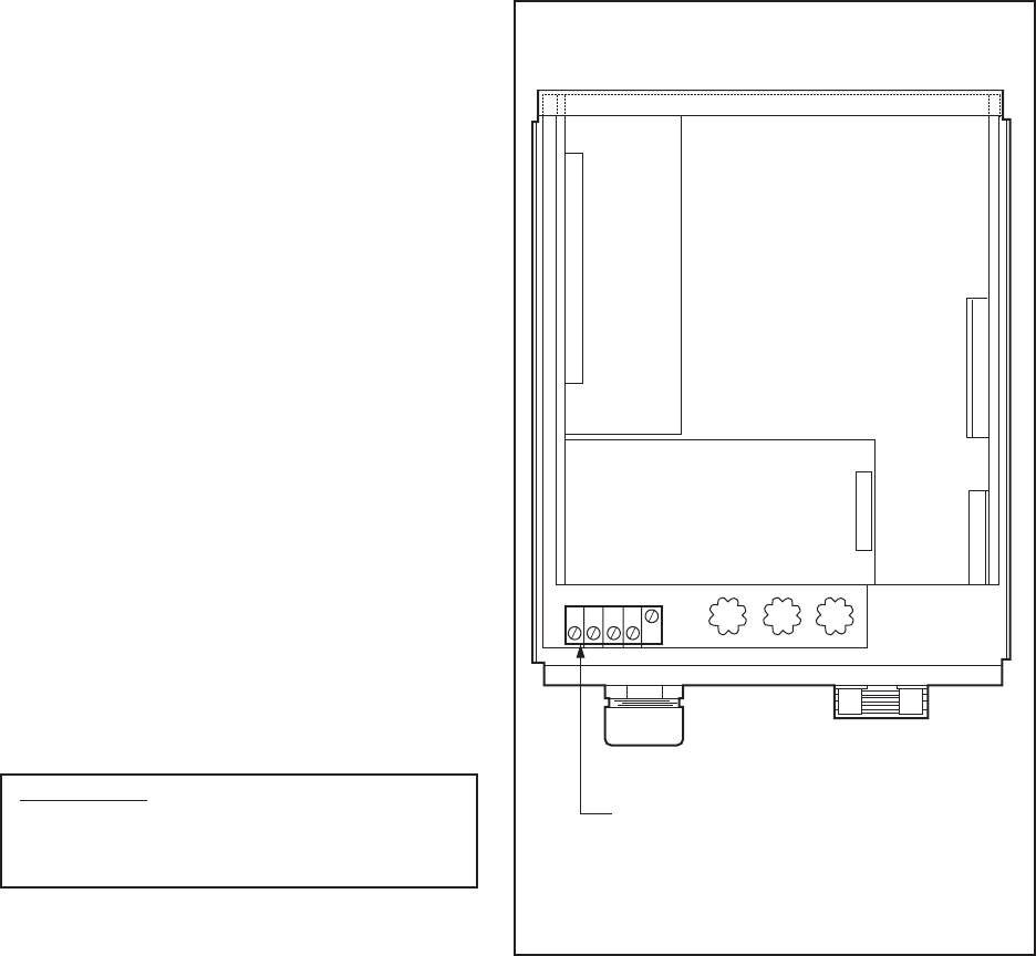
Figure 19. Coaxitron Receiver Assembly Layout
(Top View)
5.7 AUTO/RANDOM OPERATION
The A9000 Auto/Random Scan module is a plug-in
P.C. board option (See Fig. 19 for board location) for all
Coaxitron receivers. This module provides two modes
for automatically controlling pan and tilts within preset
limits — Auto Scan and Random Scan. The Random
Scan and Auto Scan functions are controlled by the
same momentary switch on the control panel labeled
AUTO and MAN. The first activation of the switch to
the AUTO position will put the pan/tilt into Random
Scan. In Random Scan operation the pan/tilt will travel
between the preset limits with a random scan period of
about 0 to 60 seconds, and a random dwell period of
between about 4 seconds and a programmable 60 to 900
seconds. At the completion of a dwell period, another
random scan period is started. The direction of this scan
period is also randomly determined. When a pan limit is
reached, scan direction is reversed automatically. A
second activation of the AUTO switch will put the pan/
tilt into continuous duty Auto Scan. After approxi-
mately 1/2 hour of auto scan, the circuit will reset to
random scan. Commanding AUTO while in Random
mode causes a shift to Auto mode and starts the half-
hour timer. Similarly, commanding AUTO while in
Auto mode causes a shift to the Random mode and zeros
the half-hour timer.
Advantages of random scan:
1. Because scan direction, scan period and dwell
period are unpredictable, unauthorized activi-
ties or intrusions are discouraged.
2. Because of the reduced duty cycle, gear train
wear, cable fatigue, drive motor wear and
temperature rise are reduced. These factors all
contribute to higher system reliability and in-
creased equipment life.
The A9000 auto/random scan plug-in module comes
equipped with an 8-pin male connector and two nylon
spacers factory installed. To install the module perform
the following steps:
WARNING: Power must be removed from re-
ceiver prior to installing A9000. Destructive fail-
ure of A9000 may result if it is plugged into a
powered motherboard.
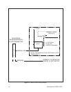
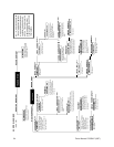
1. Locate the 8-pin female connector (J2) on the
motherboard and insert the 8-pin male connec-
tor (P5). See Figure 20 for wiring schematic.
2. Insert spacers into appropriate holes in the
motherboard and snap firmly into place.
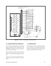
5.8 CX900TLC MANUAL/TEST MODULE
The CX900TLC Manual/Test Board is a dual purpose
plug-in module (See Fig. 19 for board location) which
permits local operation of all functions directly from the
receiver unit, and also serves to verify that the receiver
and accessories are operating properly by providing
visual confirmation. This module also aids in trouble-
shooting receiver or transmitter operational problems.
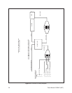
See Figure 21 for module functions and wiring sche-
matic.
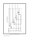
P3
1
22
TEST
MODULE
CX900TLC
RECEIVER BOARD
RX90001000ASSY (24 VAC)*
RX90001007ASSY (120/220 VAC)*
(*VOLTAGES REFER TO
OUTPUT (P/T), CAMERA.)
14
1
P2
J2
1
1
8
10
P1
P5
AUTO/RANDOM SCAN MODULE
A9000
F2 F1F3
OUTPUT
A.C. INPUT
CAUTION: HAZARDOUS VOLTAGE MAY EXIST.
3 2 1
AC
LOW
GRN
AC
HIGH
VIDEO
IN
VIDEO
OUT