


4 Pelco Manual C550M-E (8/97)
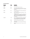
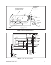
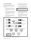
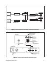
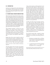
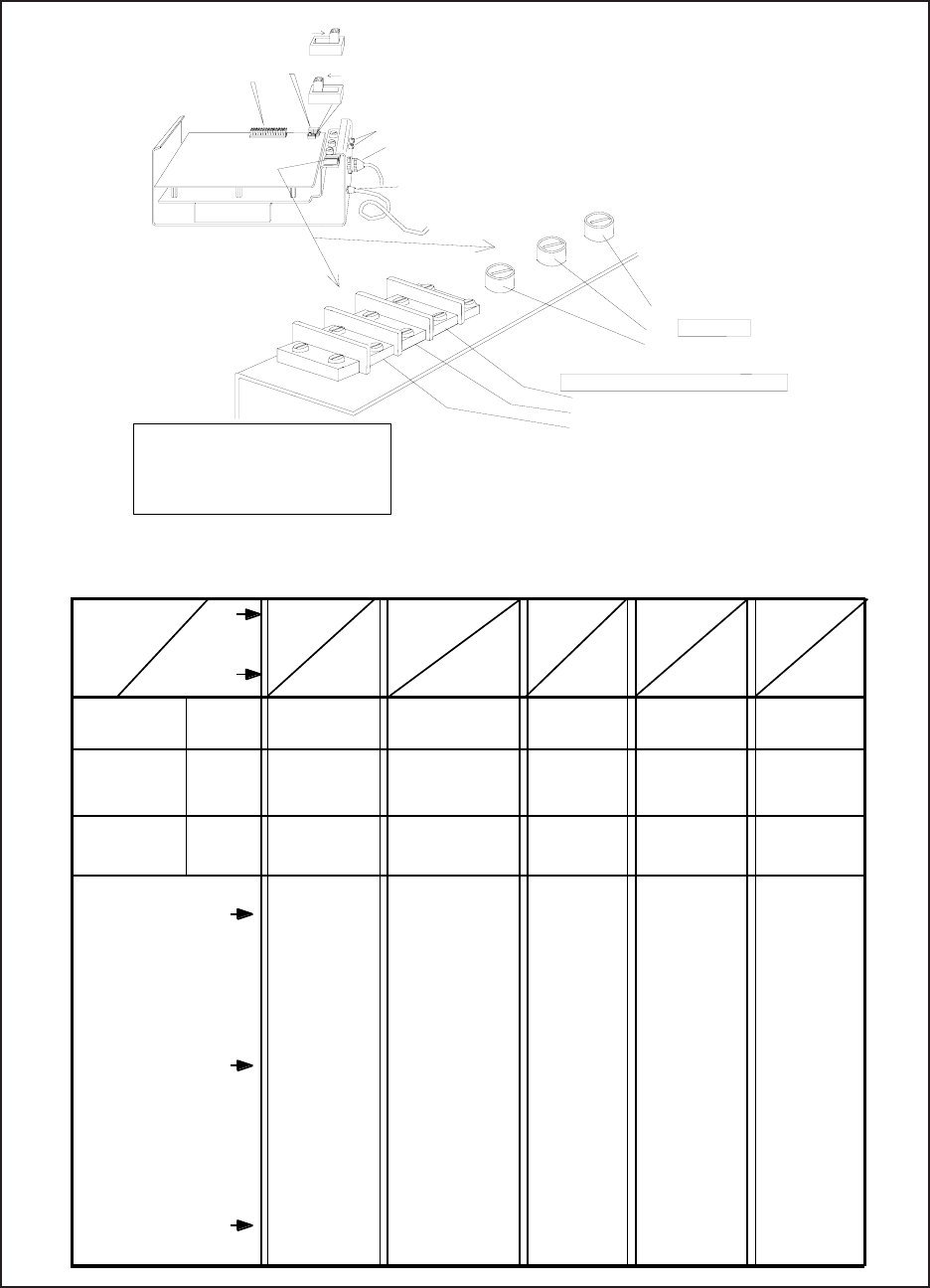
Figure 3. AC Input and Fuse Values
shown in the
"Short" position
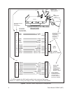
37-PIN
AMP CONNECTOR
POWER INPUT
PC BOARD
1. AC HIGH
2. GROUND
3. AC LOW
F2
F3
TRANSMITTER: F1 2/10 ASB, 3AG
shown in the
"Long" position
AC INPUT DESIGNATIONS
FUSES
RECEIVER FUSE VALUES: SHOWN BELOW
F1
BNC
CONNECTORS
P2
P1
SW 1
SW 1
**
**
**
For REV K boards, the SW1
switch positions shown above
are just reversed; i.e., "Short"
is "Long" and "Long" is "Short".
F3
F2
F1
POWER OUTPUT
INPUT P/T
VAC VAC
CX9024RX
CX9024RXI
*12VDC Camera
options use a
1/2ASB fuse
value in this
position in place
of the 2/10’s
value.
*CX9024RXI-12V
*CX9024RX-12V
CX9024RX-PP
CX9024RXI-PP
CX9024RX/220
CX9024RXI/220
CX9024RXI-PP/22
CX90224RX-PP220
*CX9024RX-12V220
CX9024RXI-12V220
WX8024RX
WX8024RXI
CX9224RX
CX9224RX-PP
CX9224RXI
CX9224RXI-PP
*CX9224RXI-12V
CX9115RX
CX9115RX-PP
CX9115RXI
CX9115RXI-PP
WX8224RX
WX8224RXI
1ASB
2/10ASB
*1/2ASB
NOT
USED
1/2ASB
1/10ASB
*1/4ASB
1/10ASB
1/10ASB
1/2ASB
1A
1ASB
2/10ASB
2/10ASB
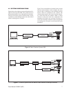
120VAC
IN
24VAC
P/T OUT
P/T
CAMERA
PC BOARD
230VAC
IN
24VAC
P/T OUT
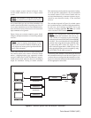
230VAC
IN
230VAC
P/T OUT
24VAC
IN
24VAC
P/T OUT
120VAC
IN
120VAC
P/T OUT
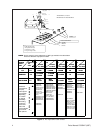
A P P L I C A B L E M O D E L S
WX8024RX/220
WX8024RXI/220
WX8115RX
NOTE:
For this manual, ignore references to “WX” type models in the table below.
These are “Wiretron” equipment models.
Additional
combinations
of equip-
ment options
are possible
depending
on custom-
er need &
availability.
This listing
covers the
most used
and/or the
most available
type units &
their options.
NOT
USED
NOT
USED
3A
CX9220RX
CX9220RX-PP
CX9220RXI
CX9220RXI-PP
WX8220RX
*12VDC camera
option uses a
1/4ASB fuse
value in place of
the 1/10’s value.
*The CX9224
option w/ 12VDC
camera uses 1
(one) fuse in the
F3 position. It is
a 3A fuse, not a
3ASB fuse. Fuse
positions F1 and
F2 are not used.