


12 Pelco Manual C550M-E (8/97)
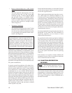
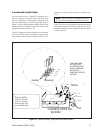
• Receiver Control Output for 12 VDC Camera
Option
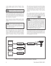
The usual output for camera power is 24 VAC
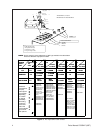
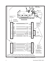
accessed at pins 9 and 14 of the 37-pin AMP
connector (see Fig. 5) where CAM AC HIGH
and AC LOW emerge as CAMERA INPUT
POWER. The output pin assignments remain the
same for 12 VDC camera power options, only
now pin 9 (WH) is positive (+) and pin 14 (WH/
YEL) is negative (-).
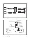
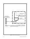
• Transmitter Video Input
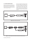
The transmitter usually provides for the 75 ohm
termination of the cable from the receiver. How-
ever, the user may alter this termination in order
to loop through and terminate further down-
stream. (See Figure 10.)
WARNING: Power for enclosure models utiliz-
ing heater/blowers cannot be tapped off the sec-
ondary of the Coaxitron receiver transformer or off
of camera AC power (see Figure 5, Pins 9 and 14).
Instead,for example, enclosure power for these
purposes could be run off of the primary of the
Coaxitron transformer and routed to the enclosure
via unused Pins 15 and 16 of the 37-Pin connector.
Although the Coaxitron control system is immune to
transient or surge disturbances, its performance can be
impaired by the presence of large ground loop voltages
between the transmitter and the receiver. The amplitude
of ground loop potential that can be tolerated varies as
a complex function of cable center conductor resis-
tance, video signal amplitude, and cable length. How-
ever, ground loop voltages that induce less than 0.5 volt
p-p into the video output of the receiver should not cause
the system to malfunction.
In general, ground loop problems will seldom be en-
countered. However, potentials as high as 10 volts p-p
between ground connections within a single building
are not unheard of. If such circumstances arise, Pelco
recommends the use of its Model GIT100 Ground
Isolation Transformer. When inserted in the cable run
between two points of different ground potential, the
effect of this potential difference on the video signal is
reduced by more than 100 times with 200 feet, and more
than 20 times with 1,500 feet of RG59 type cable. More
than one GIT100 can be utilized in situations where the
common mode voltage (CMV) exceeds 10 volts p-p.
This transformer is passive and can easily be inserted
where required at any time.
Factors that limit the distance over which the Coaxitron
can be used are transmission line attenuation and trans-
mission line signal distortion
When signal attenuation becomes large due to exces-
sive cable length, the differential amplifier in the
Coaxitron receiver can no longer detect the presence of
a control pulse train. The limitation can be overcome by
increasing the amplitude of the pulses generated by the
transmitter. This is not done without danger, however,
because associated equipment may be over-driven by
the larger signal. (Note that the presence of the control
signal is not restricted to the cable between the transmit-
ter and receiver, but will be on all signal cables down-
stream from the receiver.)
It has been stipulated that loop-through connections are
permissible in the control link, and distribution or
equalizing amplifiers are not because of their
undirectional characteristics.
Pre-equalization of the camera signal prior to feeding to
the Coaxitron receiver is generally not practical because
of the dynamic limits in the receiver video amplifier.
Post equalization of the signal (transmitter output sig-
nal) is permissible, but probably not practical. It should
be kept in mind that although the camera signal has been
deteriorated by the transmission line, the control signal
has not. Therefore, the equalized control pulses will be
extremely large and probably cause an overload in some
part of the system downstream from the equalizing
amplifier.
In the absence of an assertive control command, the
transmitter is inactive. Thus, it is possible to control one
receiver from more than one control.
5.5 COAXITRON PREPOSITION
RECEIVER
Note: The Coaxitron preposition receiver is
designed for use with Coaxitron Matrix controls
only.
The Coaxitron System utilizes linear taper precision
potentiometers as the position feedback sensors. This
feedback voltage is digitized and stored in the receiver.
The storage of the presets is held in EEPROM and is
therefore nonvolatile.