Pelco Manual C550M-E (8/97) 3
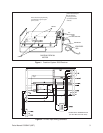
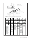
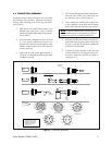
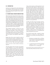
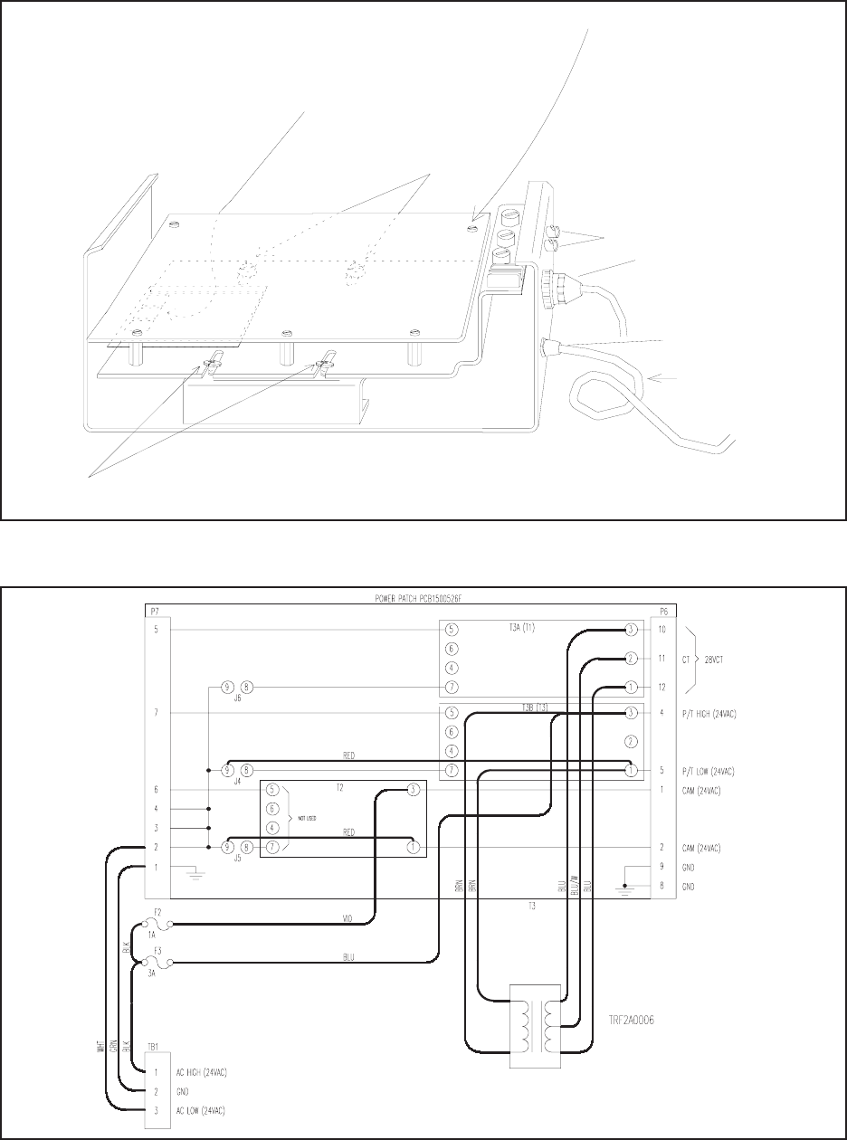
Figure 1. Coaxitron System 2000 Receiver
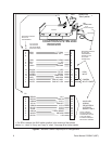
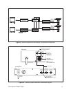
Figure 2. 24 VAC Input Wiring Schematic
T1
T2
T3
POWER INPUT
PC BOARD
SCREWS
SCREWS
AMP CONNECTOR
37-PIN
Remove PC board mounting screws
and remove the PC board.
If necessary, tag and remove
the PC board.
REMOVE POWER
CORD
COAXITRON SYSTEM 2000
RECEIVER
Remove or loosen the four patch panel mounting
screws indicated below to gain access to patch
panels T1, T2, and T3.
any affected cables attached to
BNC
CONNECTORS
COAXITRON II POWER PATCH
(24 VAC INPUT/24 VAC OUT)


