


Pelco Manual C550M-E (8/97) 13
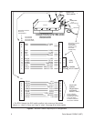
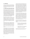
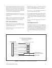
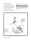
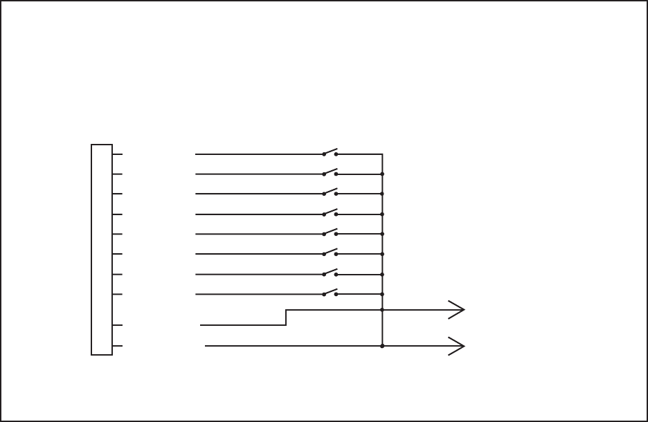
Up to 32 presets can be stored in each receiver. Up to 8
presets can be activated by alarm contacts connected to
the receiver. There is also an open collector output from
the receiver to activate an external device (such as the
CSA764) when the alarm contacts are activated. Figure
11 shows the wiring for alarmed presets.
If multiple alarms are activated, the receiver will se-
quence between the alarm presets at a 5 second dwell
time per preset.
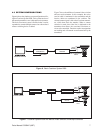
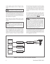
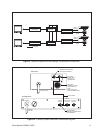
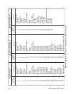
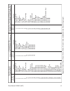
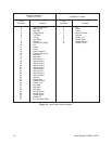
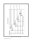
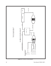
Figures 12 through 14 provide pin-to-pin connections
for preset domes, pan/tilts and lenses to the Coaxitron
receiver that are available at this revision manual.
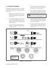
5.5.1 Power-up Routine
When a preposition receiver is first powered up, it has
a routine that it goes through to orient itself to the pan/
tilt and lens connected to it.
The routine first automatically operates the lens “zoom”
and “focus” functions.
The pan/tilt will “nod yes” if the receiver reads the
feedback voltages (preposition lens) or “nod no” if it
does not read any feedback voltages (manual lens).
This routine is a good troubleshooting indicator of
incorrect wiring of the control cable.
The second part of the routine will operate the “pan left”
and “pan right” functions. The pan/tilt will “nod yes” if
it reads only one feedback voltage (pan/tilt with limit
stops) or “nod no” if it reads two feedback voltages (SL
pan/tilt).
The total routine takes approximate 45 seconds to
complete.
5.5.2 Creating Presets
At the present time the only Coaxitron system transmit-
ters capable of creating presets are the CM7500, the
CM9500 Matrix and the MPT9500. Refer to the instruc-
tions in the product manuals (C584M, dated 2/90 or
later for CM7500 matrix, or C500M for CM9500 matrix
or C535M for the MPT9500) to create presets, if neces-
sary.
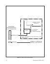
Figure 11. Wiring Diagram for Preposition Alarm Outputs
ALARM CONTACTS NORMALLY OPEN
17
18
19
20
21
22
23
24
25
26
ALARM INPUT 1
ALARM INPUT 2
ALARM INPUT 3
ALARM INPUT 4
ALARM INPUT 5
ALARM INPUT 6
ALARM INPUT 7
ALARM INPUT 8
ALARM OUTPUT
ALARM COMMON
C
OAXITRON RECEIVER
37 PIN CONNECTOR
ALARM CONDITION
OPEN COLLECTOR OUTPUT
BACK TO CSA764 ALARM INPU
T
ALARM COMMON
BACK TO CSA764
NOTE: ALARM OUTPUT MUST RETURN TO
THE CSA764 FOR THE ALARM CONDITION
TO BE SWITCHED TO THE MONITOR 1
OUTPUT OF THE MATRIX