


50
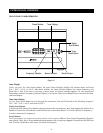
CONNECTIONS
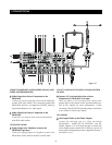
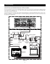
6. High-Output Flasher to the Flasher Outputs
Connect the mini-plug end of a Niles High-Output
Flasher, Model IRC-1P (FG00932), to the Flasher Output
labeled ALL. Strategically position the IRC-1P to provide
IR transmission to all source components. It adheres with
a Velcro mounting system (included).
SOURCE-COMPONENT HOME THEATER
SYNCHRONIZATION SIGNALS
7. 12V Home Theater Sync to Home Theater Sync Input
Connect the 12V Home Theater sync signal to the Home
Theater sync input with a mini-plug.
12V CONTROL SIGNALS
8. 12V Control Outputs to Voltage-Triggered Devices
The 12V control outputs, Main, and Zones 4, 5, and 6
connect to the trigger input of a voltage-activated device
(i.e., Niles AC-3) with the mini-plug end of a Niles
Accessory Cable (FG00724).
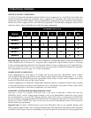
HOME THEATER CONTROL SYSTEM
9. IR Output from a Home Theater Control System to the
IR Input
Connect a Home Theater Control System to the IR Input of
the ZR-8630AV with the mini-plug end of a Niles
Accessory Cable (FG00724).
AM/FM ANTENNAS
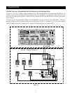
0. AM Loop Antennas
Connect the bare-wire ends of the AM Loop Antennas
(included) to the spring-loaded AM and GND terminals
on the ZR-8630AV. Then position and mount the
antennas for proper reception.
1. Coaxial Cables to FM Antenna Assembly
Connect the F-connectors on the two male-to-male
coaxial cables (included) to the two female coaxial F-
connectors on the ZR-8630AV, and to the signal splitter’s
two female coaxial F-connectors (labeled OUT).
1. Signal Splitter
The signal splitter divides the signal from the FM Dipole
Antenna to supply both FM tuners in the ZR-8630AV.
3. FM Dipole Antenna
Connect the male coaxial F-connector of the FM Dipole
Antenna (included) to the signal splitter’s single female
coaxial F-connector (labeled IN). Then position and
mount the antenna for proper reception.
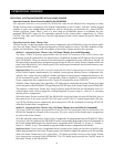
SPEAKERS
1. Zones 1-6
Use Niles no-strip connectors to attach wires from the
ZR-8630AV to the speakers in the listening zones.
1. Zone Video Outputs
Six RCA jacks provide zoned output connections for TVs
and video displays.
PREAMPLIFIER ZONE OUTPUTS
1. Zones 1-6 (4-6 set to Variable Mode)
For more power in a zone, connect Individual Zone
Preamplifier Outputs 1-6 to an external amplifier with
male-to-male RCA audio cables. (See System
Configurations 8 and 9 for more details.)
1. Zones 4-6 Set to Fixed Mode
For more rooms/power in a zone, connect Individual
Zone Preamplifier Outputs 4-6 (set to fixed output mode)
to an external amplifier with male-to-male RCA audio
cables. (See Configuration 10 for more details.)
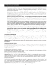
KEYPAD MODULES
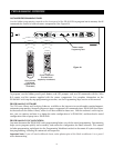
1. Keypads to Keypad Inputs for Zones 1-6
Connect the keypads to the zoned keypad inputs with
four-pair twisted cable terminated with male RJ-45 plugs.
(See page 47, Terminating Four-Pair Twisted Cable, for
more information.)
SYSTEM EXPANSION
1. System Expansion Input to System Expansion Output
Connect multiple ZR-8630AV units with four-pair
twisted cable, terminated with male RJ-45 plugs, using
the system-expansion input and output terminals. Make
connections from the input of one ZR-8630AV to the
output of another, and so on. (See page 47, Terminating
Four-Pair Twisted Cable, for more information.)
AC POWER
1. Removable AC Power Cord
Connect the removable AC power cord (included with
the ZR-8630AV) to the power-cord socket and to an AC
power outlet.
6
7
8
9
10
11
12
13
14
15
16
17
20
18
19