1
CONVENTIONS FOLLOWED IN THIS MANUAL
The writing conventions described below have been
followed to simplify instructions and avoid unnecessary
repetition.
ATTENTION: MOST PROCEDURES REQUIRE THAT YOU PRESS AN
APPROPRIATE KEY IN EACH STEP WITHIN APPROXIMATELY 10
SECONDS, OR THE PREVIOUS MODE WILL BE RESTORED.
SUPPLIED ACCESSORIES
Microphone
U.S.A./ Canada/
General (some): MC-53DM
Europe/
General (some): MC-45
DC power cable
Transceiver fuse (15 A)
Mounting bracket
Mounting bracket screws
Microphone hanger
(U.S.A./ Canada only)
Microphone hanger screws
(U.S.A./ Canada only)
Warranty card
(U.S.A./ Canada/ Europe only)
Instruction manual
T91-0568-XX
T91-0396-XX
E30-2111-XX
F51-0017-XX
J29-0632-XX
N99-0331-XX
1
1
1
1
1
1 set
Accessory
Part Number
Quantity
1
2
2
1
—
1
1
2
1
B62-0678-XX
N46-3010-XX
J19-1526-XX
What to doInstruction
Press and release KEY.
Press and hold KEY until the
function begins.
Press KEY1 momentarily,
release KEY1, then press
KEY2.
With transceiver power OFF,
press and hold KEY, then turn
ON the transceiver power by
pressing [PWR].
Press and hold [F] for 1
second or longer, then press
KEY.
Press [F] momentarily, release
[F], then press and hold KEY
for 1 second or longer.
Press and hold [F] down, then
press KEY.
Press [KEY].
Press
[KEY] (1 s).
Press
[KEY1], [KEY2].
Press
[KEY]+ POWER ON.
Press
[F] (1 s), [KEY].
Press
[F], [KEY] (1 s).
Press
[F] + [KEY].
1
The MC-53DM and MC-45 microphones are also sold as
optional accessories {page 83}.
2
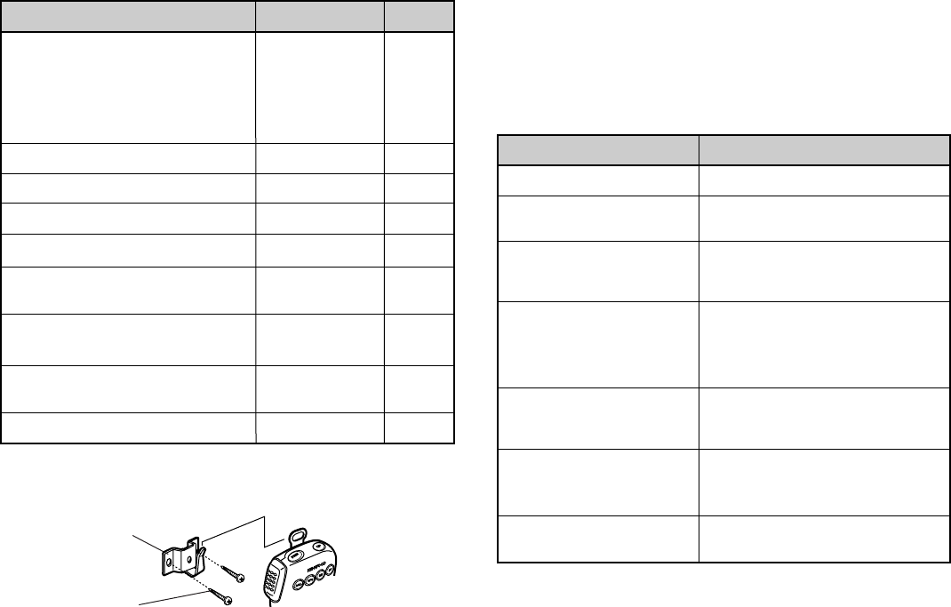
Attach the microphone hanger at an appropriate position.
Microphone
hanger screw
Microphone
hanger


