


P.CONT
ILLUMI
ANT.
CONT
MUTE
REMOTE
CONT
STEERING
WHEEL
REMOTE
INPUT
–
+
L
R
L
R
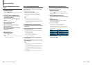
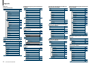
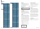
FM/AM antenna input
Front output
Fuse(10A)
Microphone
(Accessory5)
Microphone input
White/Black
Gray/Black
Green/Black
Purple/Black
White
Gray
Green
Purple
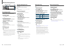
To front left speaker
To front right speaker
To rear right speaker
To rear left speaker
Red (Ignition wire)
Yellow (Battery wire)
Black (Ground wire) · (To car chassis)
Ignition key
switch
Car fuse box
(Main fuse)
ACC
Car fuse
box
Battery
If no connections are made, do not let the wire come out from the tab.
Blue/White (Power control wire)
Blue (Antenna control wire)
Orange / White (Dimmer control wire)
When using the optional power amplifier, connect this wire to its power
control terminal.
To car light control switch
Depending on what antenna you are using, connect either to the control
terminal of the motor antenna, or to the power terminal for the booster
amplifier of the film-type or short pole type antenna.
(Max.300mA,12V)
Sub Woofer output
Brown (Mute control wire)
Rear output
To use the steering wheel remote control feature, you need to an
exclusive remote adapter (not supplied) matches your car is required.
Light Blue/Yellow (Steering remote
control wire)
To SiriusXM Connect Vehicle Tuner (optional accessory)
To connect the Kenwood navigation system, consult your navigation
manual.
USB connector
(0.8m(2.7ft))
To USB device
⁄
Do not remove the cap
when you do not use the
USB cable. The connector
will cause the unit to
malfunction if it gets in
touch with any metallic
part of the vehicle.
Wiring harness
(Accessory1)
AUX input (Stereo)
Use the mini-plug which is stereo type
and does not have any resistance.
(3.5mm(1/8”)ø)
Antenna Cord
83
|
KDC-X996/ KDC-BT952HD
English
|
84
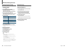
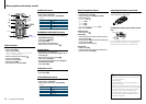
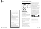
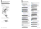
Connecting Wires to Terminals Installing/Removing the unit
non-Japanese cars
Bend the tabs of the mounting
sleeve with a screwdriver or the
like and attach it in place.
⁄
• Makesurethattheunitisinstalledsecurelyinplace.Ifthe
unit is unstable, it may malfunction (for example, the sound
may skip).
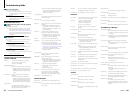
Japanese cars
1
Remove the hard rubber frame with reference to
<Removing the hard rubber frame>.
2
Align the holes in the unit (two locations on each
side) with the vehicle mounting bracket and secure
the unit with the accessory screws.
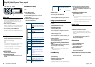
8 mm
MAX.
ø5mm
ø5mm
8mm
MAX.
T
N
T
N
T/N
T: Toyota cars
N: Nissan cars
Accessory3...for Nissan car
Accessory4...for Toyota car
3
4
Removing the hard rubber frame
1
Engage the catch pins on the removal tool and
release the two locks on the upper part of frame.
Lift up and pull the frame forward as shown in the
figure.
Catch
Lock
Accessory2
Removal tool
2
When the upper part of frame is removed, remove
the lower part of frame.
⁄
• Theframecanberemovedfromthebottomsideinthe
same manner.
Removing the Unit
1
Remove the hard rubber frame with reference to
<Removing the hard rubber frame>.
2
Detach the faceplate.
3
Insert the two removal tools deeply into the slots
on both sides as shown.
4
Lower the removal tool toward the bottom, and
then pull out the unit halfway while pressing the
removal tool towards the inside.
Accessory2
¤
• Becarefultoavoidinjuryfromthecatchpinsonthe
removal tool.
5
Pull the unit all the way out with your hands, being
careful not to drop it.
¤ CAUTION
Install this unit in the console of your vehicle.
Do not touch the metal parts of this unit during and
shortly after use of the unit. Metal parts such as the
heat sink and enclosure become hot.