


7
English
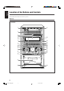
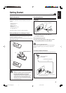
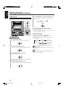
1 If the cords are covered with insulation, remove a
short section of insulation at the end of each cord
by twisting and pulling it off.
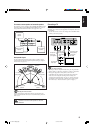
2 Press and hold the clamp of the AM LOOP
terminals on the rear of the unit.
3 Insert the AM loop antenna to the AM LOOP
terminals as illustrated.
4 Release your finger from the clamp.
5 Turn the AM loop antenna until you have the best
reception.
To connect an outdoor AM antenna
When reception is poor, connect a single vinyl-covered wire to the
AM EXT terminal and extend it horizontally. The AM loop antenna
must remain connected.
For better reception of both FM and AM
• Make sure the antenna conductors do not touch any other terminals
and connecting cords.
• Keep the antennas away from metallic parts of the unit, connecting
cords, and the AC power cord.
AM antenna
Vinyl-covered wire
(not supplied)
AM loop antenna
(supplied)
1
5
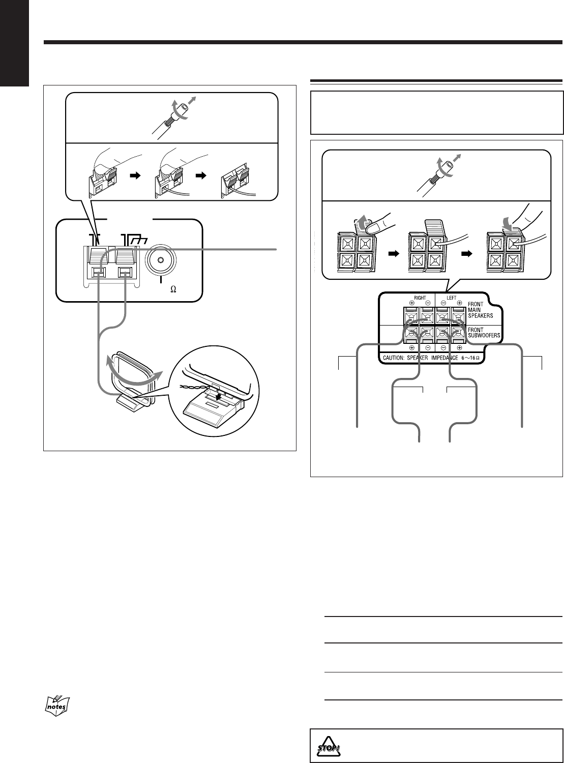
Connecting Speakers
IMPORTANT: Use only speakers with the same speaker
impedance as indicated by the speaker terminals on the
rear of the unit.
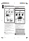
1 If the cords are covered with insulation, remove a
short section of insulation at the end of each cord
by twisting and pulling it off.
2 Open the clamp of the speaker terminals on the
rear of the unit.
3 Insert the end of the speaker cord into the
terminal as illustrated.
Match the same polarity: (+) to (+) and (–) to (–).
Speaker
(+) (–)
FRONT MAIN
SPEAKERS
FRONT
SUBWOOFERS
4 Close the speaker terminals.
DO NOT connect more than one speaker to each
speaker terminal.
23
Speaker
cords
(black/
blue)
Speaker
cords
(black/
blue)
Speaker cords
(black/red)
From right
front main
speaker
terminal
From left
front main
speaker
terminal
From front
subwoofer terminal
1
2
ANTENNA
AM EXT
AM
LOOP
FM 75
COAXIAL
3
4
Getting Started (continued)
4
Blue Black
Red Black
Terminal color
01-13HX-Z77&55[U]6.p65 03.8.18, 10:42 AM7