


10
(+) terminals on the AVR580 to the red (+)
terminals on the speakers and the black
(–) terminals on the AVR580 to the black
(–) terminals on the speakers. See page
17 for more information on speaker
polarity.
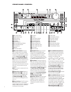
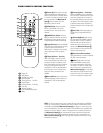
¶ Fan Vents: These ventilation holes
are the output of the AVR580’s airflow
system. To ensure proper operation of the
unit and to avoid possible damage to del-
icate surfaces, make certain that these
holes are not blocked and that there is at
least three inches of open space between
the vent holes and any wooden or fabric
surface. It is normal for the fan to remain
off at most normal volume levels. An
automatic termperature sensor turns the
fan on only when it is needed.
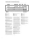
• Center Speaker Outputs: Connect
these outputs to the matching + and –
terminals on your center channel speaker.
In conformance with the new CEA color-
code specification, the green terminal is
the positive, or “+,” terminal that should
be connected to the red (+) terminal on
speakers with the older color-coding.
Connect the black (–) terminal on the AVR
to the black (–) terminal on your speaker.
(See page 17 for more information on
speaker polarity.)
ª Surround Back/Multiroom
Speaker Outputs:
These speaker termi-
nals are normally used to power the sur-
round back left/surround back right
speakers in a 7.1 channel system. How-
ever, they may also be used to power the
speakers in a second zone, which
will
receive the output selected for a multi-
room system.
To change the output fed to
these terminals from the default of the
Surround Back speakers to the Multiroom
Output, you must change a setting in the
Advanced Menu of the OSD system. See
page 37 for more information on configur-
ing this speaker output. In normal sur-
round system use, the brown and black
terminals are the surround back left chan-
nel positive (+) and negative (–) connec-
tions and the tan and black terminals are
the surround back right positive (+) and
negative (–) terminals. For multiroom use,
connect the brown and black SBL termi-
nals to the red and black connections on
the left remote zone speaker and connect
the tan and black SBR terminals to the
red and black terminals on the right
remote zone speaker.
‚ AC Power Cord Jack: Connect the
AC power cord to this jack when the
installation is complete. To ensure safe
operation, use only the power cord sup-
plied with the unit. If a replacement is
required it must be of the same type and
capacity.
Depending on the electrical requirements
in your area or the wiring in your home,
the power cords included with your AVR
may not be the correct ones, and you may
need to contact your local JBL distributor
to obtain the correct power cord.
⁄ Region Selector: Select the position
corresponding to the country in which the
AVR will be used (C, S or K) so that the
video standard and the FM tuner’s fre-
quency increments will be correct. See
page 35 for more information on setting
the
Region Selector ⁄.
IMPORTANT NOTE:
Any adjustments
made to the
Region Selector ⁄ will
not take effect unless the unit is first
fully turned off by pressing the
Main
Power Switch
1 until it pops out and
the word “OFF” appears on the top of
the button.
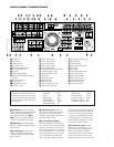
¤ Video Monitor Outputs: Connect
these jacks to the composite or S-Video
input of a TV monitor or video projector to
view the on-screen menus and the output
of any standard video source selected by
the receiver’s video switcher.
‹ DVD Video Inputs: Connect the com-
posite or S-Video outputs of a DVD player
or other video source to these jacks.
› Video 1 Video Inputs: Connect the
composite or S-Video PLAY/OUT jacks of
a VCR or other video source to these
jacks.
fi Video 1 Video Outputs: Connect the
composite or S-Video REC/IN jacks of a
VCR or other video recording device such
as a DVD recorder or PVR to these jacks.
fl Video 2 Video Inputs: Connect the
composite or S-Video PLAY/OUT jacks of
a VCR or other video source to these
jacks.
‡ Video 2 Video Outputs: Connect the
composite or S-Video REC/IN jacks of a
VCR or other video recording device such
as a DVD recorder or PVR to these jacks.
° Video 3 Video Inputs: Connect the
composite or S-Video PLAY/OUT jacks of
a VCR or other video source to these
jacks.
· Component Video Monitor
Outputs:
Connect these outputs to the
component video inputs of a video projec-
tor or monitor. When a source connected
to one of the
Component Video Inputs
ab is selected, the signal will be sent
to these jacks.
a Component Video 1 Inputs: Connect
the Y/Pr/Pb component video outputs of
a DVD player, HDTV set-top converter,
satellite receiver or other video source
device with component video outputs to
these jacks.
b Component Video 2 Inputs: Connect
the Y/Pr/Pb component video outputs of
an HDTV set-top converter, satellite
receiver or other video source device with
component video outputs to these jacks.
c RS-232 Port: This jack is used to
enable the AVR580 to be controlled by
an external computer or programmable
remote system that uses RS-232 com-
mands. Due to the complexity of RS-232
connections, we recommend that they be
made by a trained and qualified custom
installer. See page 18 for more informa-
tion on the RS-232 control port.
d Multiroom IR Input: Connect the out-
put of an IR sensor in a remote room to
this jack to operate the AVR580’s multi-
room control system.
e Remote IR Input: If the AVR580’s
front-panel IR sensor is blocked due to
cabinet doors or other obstructions, an
external IR sensor may be used. Connect
the output of the sensor to this jack.
f Remote IR Output: This connection
permits the IR sensor in the receiver to
serve other remote controlled devices.
Connect this jack to the “IR IN” jack on
JBL (or other compatible) equipment.
g Coaxial Digital Audio Output:
Connect this jack to the coaxial digital
input of a CD-R/RW, MiniDisc or other
digital recorder.
h Multiroom Audio Outputs: Connect
these jacks to the optional external audio
power amplifier and video distribution
system that delivers the source selected
for multizone distribution.
i Optical Digital Audio Output:
Connect this jack to the optical digital
input connector on a CD-R/RW, MiniDisc
or other digital recorder.