


18
2. Connect the analog audio and video
outputs of a satellite receiver, cable TV
converter or any other video source to
the
Video 2 Audio and Video Input
Jacks
fla.
3. Connect the analog audio and video
outputs of a DVD or laser disc player
to the
DVD Audio and Video Inputs
‹k.
4. Connect the digital audio outputs of
a DVD player, satellite receiver, cable
box or HDTV converter to the appropriate
Optical or Coaxial Digital Inputs
&*.
5. If you are using your television as a
signal source, then connect its analog
audio outputs to the
Video 3 Audio
Input Jacks
. NEVER connect the
TV’s video outputs to the
Video 3
Video Input Jacks
° or to any other
inputs on the AVR580. If you are not
using your television as a signal source
(e.g., if you are separately connecting
a cable TV box to the
Video 2 Audio
and Video Input Jacks fl ), then
do not connect any of the TV’s outputs
to any inputs on the AVR580. In that
case you should only connect the AVR’s
Video Monitor Outputs ¤ to the TV
as indicated in paragraph 6 below.
However, you may still find it conven-
ient to program the VID3/TV input
selector on the remote control for your
TV as described on page 41. If you pre-
fer, you may connect another type of
video source, such as a second VCR,
to the AVR580’s
Video 3 Audio and
Video Input Jacks ° . You may
then reassign that device type to the
VID3/TV input selector on the remote
as described on page 45, and you will
not be able to control your TV using
the AVR remote.
6. Connect the
Video Monitor Output
¤ jacks on the receiver to the com-
posite or S-Video input of your televi-
sion monitor or video projector.
7. If your DVD player and monitor both
have component video connections,
connect the component outputs of the
DVD player to the
Component Video
1 Inputs
a. Even when component
video connections are used, the audio
connections should still be made to
either the analog
DVD Audio Inputs
k or any of the Optical or Coaxial
Digital Input Jacks
. Note,
however, that the
Coaxial 1 Digital
Audio Input is assigned to the
DVD source by default. For more infor-
mation on reassigning the digital
inputs to various sources, see pages
22 and 32. The
Component Video 1
Inputs
a are assigned to the DVD
source and may not be reassigned.
8. If another device with component video
outputs is available, connect it to
the
Component Video 2 Inputs b.
The audio connections for this device
should be made to either the
Video 2
Audio Inputs
or any of the
Optical or Coaxial Digital Input
Jacks
. The
Component
Video 2 Inputs
b
are assigned to the
Video 2 source and may not be reas-
signed. If you are using a cable televi-
sion, satellite receiver, HDTV or other
video set-top box that has component
video outputs, it is recommended that
you designate it as the Video 2 source
when programming the remote control.
9. If the component video inputs are
used, connect the
Component Video
Monitor Outputs
· to the compo-
nent video inputs of your TV, projector
or display device.
10. If you have a camcorder, video game
or other audio/video device that is
connected to the AVR on a temporary
rather than permanent basis, connect
the audio, video and digital audio out-
puts of that device to the
Front-Panel
Inputs
&*(Ó. A device con-
nected here is selected as the Video 4
input, and the digital inputs must be
assigned to the Video 4 input. (See
page 22 for more information on input
configuration.)
Video Connection Notes:
• When the component video jacks are
used, the on-screen menus are not visi-
ble and you must switch to the stan-
dard composite or S-Video input on
your TV to view them.
• The AVR580 will accept either stan-
dard composite, S-Video or Y/Pr/Pb
component video signals. However, it
will not convert composite or S signals
to component video.
• Component and composite video sig-
nals may only be viewed in their native
formats. Thus both connections must
be made from the AVR580 to the TV
if both composite video and S-Video
sources are used, and the appropriate
input on the TV must be selected.
However, only one video connection
should be made between the source
(e.g., VCR) and the AVR580.
• Only the video cables (the yellow com-
posite video; the S-Video or the green,
red and blue component video cables)
need to be connected to the TV or
video display. The volume on the TV
should be reduced to minimum.
System and Power
Connections
The AVR580 is designed for flexible use
with multiroom systems, external control
components and power amplifiers.
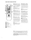
Main Room Remote Control
Extension
If the receiver is placed behind a solid or
smoked glass cabinet door, the obstruc-
tion may prevent the remote sensor from
receiving commands. In this event, an
optional remote sensor may be used.
Connect the output of the remote sensor
to the
Remote IR Input e jack.
If other components are also prevented
from receiving remote commands, only
one sensor is needed. Simply use this
unit’s sensor or a remote eye by running a
connection from the
Remote IR Output
f jack to the Remote IR Input jack on
compatible equipment.
Multiroom IR Link
The remote room IR receiver should be
connected to the AVR580 via standard
coaxial cable. Plug the IR connection cable
into the
Multiroom IR Input d jack on
the AVR580’s rear panel.
If other compatible source equipment is
part of the main room installation, the
Remote IR
Output f jack on the rear
panel should be connected
to the IR IN
jack on source equipment. This will
enable the remote room location to
control source equipment functions.
NOTE: All remotely controlled compo-
nents must be linked together in a “daisy
chain.” Connect the
IR OUT jack of one
unit to the
IR IN of the next to establish
this chain.
34
31
37
31
34
31
40
37
40
34
31