


9
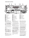
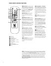
REAR-PANEL CONNECTIONS
¡ AM Antenna: Connect the AM loop
antenna supplied with the receiver to these
terminals. If an external AM antenna is
used, make connections to the
AM and
GND terminals in accordance with the
instructions supplied with the antenna.
™ FM Antenna: Connect the supplied
indoor (or an optional external) FM antenna
to this terminal.
£ Preamp Outputs: Connect these
jacks to an optional, external power
amplifier for applications where higher
power is desired.
¢ Subwoofer Output: Connect this
jack to the line-level input of a powered
subwoofer. If an external subwoofer
amplifier is used, connect this jack to the
subwoofer amplifier input.
∞ Surround Speaker Outputs:
Connect these outputs to the matching +
and – terminals on your surround channel
speakers. In conformance with the new
CEA color-code specification, the blue ter-
minal is the positive, or “+,” terminal that
should be connected to the red (+) termi-
nal on the Surround Left speaker with
older color-coding, while the gray termi-
nal should be connected to the red (+) ter-
minal on the Surround Right speaker with
the older color-coding. Connect the black
(–) terminal on the AVR580 to the match-
ing black negative (–) terminals for each
surround speaker. (See page 17 for more
information on speaker polarity.)
§ Front Speaker Outputs: Connect
these outputs to the matching + or – ter-
minals on your left and right speakers.
When making speaker connections
always make certain to maintain correct
polarity by connecting the color-coded
(white for front left and red for front right)
¡ AM Antenna
™ FM Antenna
£ Preamp Outputs
¢ Subwoofer Output
∞ Surround Speaker Outputs
§ Front Speaker Outputs
¶ Fan Vents
• Center Speaker Outputs
ª Surround Back/Multiroom Speaker
Outputs
‚ AC Power Cord Jack
⁄ Region Selector
¤ Video Monitor Outputs
‹ DVD Video Inputs
› Video 1 Video Inputs
fi Video 1 Video Outputs
fl Video 2 Video Inputs
‡ Video 2 Video Outputs
° Video 3 Video Inputs
· Component Video Monitor Outputs
a Component Video 1 Inputs
b Component Video 2 Inputs
c RS-232 Port
d Multiroom IR Input
e Remote IR Input
f Remote IR Output
g Coaxial Digital Audio Output
h Multiroom Audio Outputs
i Optical Digital Audio Output
j CD Audio Inputs
k DVD Audio Inputs
UOptical Digital Audio Inputs
V Tape Inputs
W Tape Outputs
X Coaxial Digital Audio Inputs
Y Video 1 Audio Inputs
Z Video 1 Audio Outputs
a Video 2 Audio Inputs
b 8-Channel Direct Inputs
c Video 2 Audio Outputs
d Video 3 Audio Inputs
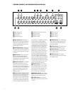
NOTE: To assist in making the correct
connections for multichannel input, out-
put and speaker connections, all connec-
tion jacks and terminals are color-coded
in conformance with the latest CEA stan-
dards as follows:
Front Left: White
Front Right: Red
Center: Green
Surround Left: Blue
Surround Right: Gray
Surround Back Left: Brown
Surround Back Right: Tan
Subwoofer: Purple
Digital Audio: Orange
Composite Video: Yellow
Component Video “Y”: Green
Component Video “Pr”: Red
Component Video “Pb”: Blue