


117
Net/USB
—Continued
Network Requirements
■
Ethernet Network
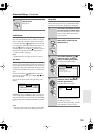
The AV receiver’s Ethernet port supports 10Base-T. For
best results, a 100Base-TX switched Ethernet network is
recommended. Although it’s possible to play music on a
computer that’s connected to the network wirelessly,
playback may be unreliable, so wired connections are
recommended.
■
Ethernet Router
A router manages the network, routing data and supply-
ing IP addresses. Your router must support the following:
•NAT (Network Address Translation). NAT allows sev-
eral networked computers to access the Internet simul-
taneously via a single Internet connection. The AV
receiver needs Internet access for Internet radio.
• DHCP (Dynamic Host Configuration Protocol).
DHCP supplies IP addresses to network devices,
allowing them to configure themselves automatically.
•A router with a 100Base-TX switch built-in is recom-
mended.
Some routers have a modem built-in, and some ISPs
require you to use specific routers. Please consult your
ISP or computer dealer if you’re unsure.
■
CAT5 Ethernet cable
Use a shielded CAT5 Ethernet cable (straight-type) to
connect the AV receiver to your home network.
■
Internet Access (for Internet radio)
To receive Internet radio, your Ethernet network must
have Internet access. A narrowband Internet connection
(e.g., 56K modem, ISDN) will not provide satisfactory
results, so a broadband connection is strongly recom-
mended (e.g., cable modem, xDSL modem, etc). Please
consult your ISP or computer dealer if you’re unsure.
Notes:
•To receive Internet radio with the AV receiver, your
broadband Internet connection must be working and
able to access the Web. Consult your ISP if you have
any problems with your Internet connection.
• The AV receiver uses DHCP to configure its network
settings automatically. If you want to configure these
settings manually, see page 122.
• The AV receiver does not support PPPoE settings, so
if you have a PPPoE-type Internet connection, you
must use a PPPoE-compatible router.
• Depending on your ISP, you may need to specify a
proxy server to use Internet radio. If your computer is
configured to use a proxy server, use the same settings
for the AV receiver (see page 122).
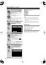
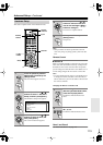
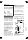
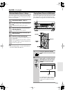
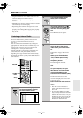
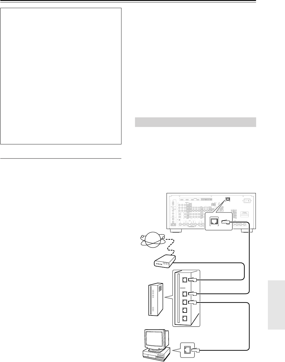
To connect the AV receiver to your home network, plug
one end of a shielded CAT5 Ethernet cable into the AV
receiver’s ETHERNET port, and plug the other end into
a LAN port on your router or switch.
The following diagram shows how you can connect the
AV receiver to your home network. In this example, it’s
connected to a LAN port on a router, which has a 4-port
100Base-TX switch built-in.
The AV receiver’s NETWORK indicator lights up when
the AV receiver is connected to the network. It flashes if
a connection cannot be established.
Minimum system requirements for Windows
Media
®
Player 11 (for Windows
®
XP)
Operating system
Windows
®
XP Home Edition (SP2), Windows
®
XP Profes-
sional (SP2), Windows
®
XP Tablet PC Edition (SP2), Update
Rollup 2 for Windows
®
XP Media Center Edition 2005
(KB900325), October 2006 Update Rollup for Windows
®
XP Media Center Edition (KB925766)
Processor:
233 MHz Intel
®
Pentium
®
II,
Advanced Micro Devices (AMD), etc.
Memory:
64 MB
Hard disk:
200 MB of free space
Drive:
CD or DVD drive
Modem:
28.8 kbps
Sound card:
16-bit sound card
Monitor:
Super VGA (800 x 600)
Video card:
64 MB VRAM, DirectX
®
9.0b
Software:
Microsoft
®
ActiveSync
®
(only when
using a Windows Mobile
®
-based
Pocket PC or smartphone)
Web browser:
Microsoft
®
Internet Explorer
®
6 or
Netscape 7.1
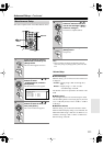
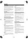
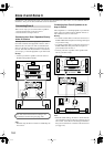
Connecting the AV Receiver
FRONT L
(BTL)
FRONT R
(BTL)
V
S
MONITOR
OUT
ZONE 2
OUT
RS232
DIGITAL
COAXIAL
OPTICAL
REMOTE
CONTROL
IN 1
IN 1
IN 2
IN IN IN IN
PHONO
ZONE2 L
FRONT R FRONT LSURR R CENTER SURR L
SURR BACK R
CD TAPE AUX 1
GAME/TV
GAME/TVCBL/SAT
CBL/SAT
AUX 1 VCR/DVR
VCR/DVR DVD
DVD
GND
IN 2
IN 3
LL
RR
ASSIGNABLE
(DVD)
(CBL/SAT)
(VCR/DVR)
(GAME/TV)
(CD)
OUT
OUT
IN IN
OUT
IN IN FRONT FRONTCENTER
SUBWOOFER SUBWOOFER
CENTERSURR SURR
MULTI CH
PRE OUT
SURR BACK SURR BACK
AC INLET
Bi-AMP
SURR BACK L
Bi-AMP
ETHERNET
HDMI
IN 1IN 2IN 3IN 4
ASSIGNABLE
OUT
MAIN
OUT
SUB
ZONE2 R
AM
ANTENNA
FM75
COMPONENT VIDEO
ASSIGNABLE
IN 3
Y
C
B
/P
B
C
R
/P
R
IN 2 IN
1(DVD)
MONITOR
OUT 1
MONITOR OUT 2
/ZONE 2 OUT
V
S
ZONE 2ZONE 3
PRE OUT
L
R
SW
AB
IR
12V TRIGGER OUT
B
OUT
C
ETHERNET
DTR-8.8
Internet
radio
Modem
Router
Computer or media server
LAN/Ethernet port
WAN port
LAN port
LAN port