


25
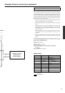
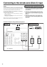
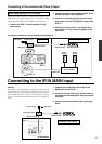
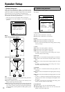
When using the ZONE 2 OUT terminals
The ZONE 2 OUT terminal is a constant output. Connect to the
LINE input of the amplifier (CD, tape, etc.). Adjust the volume
with the amplifier connected to the ZONE 2 OUT terminal.
1. Connect the DTR-7.1 to the amplifier for the
remote zone.
2. Connect the remot zone speaker cables to the
speaker terminals on the amplifier.
3. Install the connecting block in the main zone
and connect it to the IR IN ZONE 2 input at the
DTR-7.1.
4. Install the remote sensor in the remote zone
and connect it to the connecting block in the
main zone.
Connecting to the remote zone (Zone 2) input
Connection example for Onkyo’s Multi-room System kit
R
R
R
L
L
L
P
B
P
R
Y
P
B
P
R
Y
P
B
P
R
Y
COMPONENT
VIDEO
REMOTE
CONTROL
PRE
OUT
R
L
(
SB
)
ANTENNA
VIDEO
1
V
IDEO
2
DVD
MON
ITOR
OUT
V
IDEO
3
R
L
INPUT 1
INPUT 2
OUTPUT
VIDEO
S VIDEO
GND
DIGITAL
OUTPUT
(
OPTICAL
)
DIGITAL
INPUT
(
OPTICAL
)
DIGITAL
INPUT
(
COAXAL
)
1
2
1
2
FRONT
SURR
SURR
BACK
SUB
WOOFER
MULTI CHANNEL
INPUT
FRONT
SURR
SURR
BACK
SUB
WOOFER
OUT
TAPE
CD
PH
R
L
VIDEO
S VIDEO
OUT
OUT
I
N
I
N
I
N
I
N
FRONT
SPEAKERS
SURR
SPEAKERS
SURR
BACK
SPEAKER
ZONE 2
SPEAKERS
CENTER
SPEAKER
CENTER
MAIN
ZONE 2
(
SB
)
CENTER
R
L
AC OUTLETS
AC 120V 60Hz
SWITCHED
TOTAL 120W 1A MAX.
AM
IN
FM
75
12 V
TRIGGER
AB
RS 232
AC INLET
MODEL NO.
DTR-7.1
AV RECEIVER
CAUTION:
SPEAKER IMPEDANCE
6 OHMS MIN. PER EACH
SPEAKER TERMINAL
ZONE 2
MAIN
IR IN
ZONE
2
OUT
R
L
ZONE
2
OUT
R
L
ZONE 2
MAIN
IR IN
HOME THEATER CONTROLLER
RC-418M
Main zone
Remote sensor Remote controller
Zone 2
speaker
Zone 2
speaker
Zone 2 amplifier
Signal flow
Connecting block
DTR-7.1
Mini plug cable
Power supplyWall outlet
Remote zone (Zone 2)
LINE input
A
NTENNA
R
L
AM
FM
75
ZONE 2
MAIN
IR IN
12 V
TRIGGER
A
B
HOME THEATER CONTROLLER
RC-418M
Outside of the cabinet
Remote sensor Remote controller
Mini plug cable
In the cabinet
Power supply Wall outlet
Connecting block
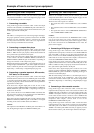
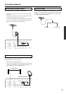
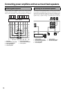
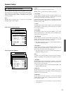
Connecting to the IR IN MAIN input
Outline
If the DTR-7.1 is located inside a cabinet or other enclosure where
the infrared beams from the remote controller cannot enter, then
operation with the remote controller will not be possible. In such a
case, it will be necessary to install a remote sensor at a location
outside of the cabinet for the infrared beams from the controller to
reach.
1. Connect the connecting block to the IR IN
MAIN input at the DTR-7.1.
2. Install the remote sensor at a location where it
can detect the infrared beams from the remote
controller.
3. Connect the remote sensor to the connecting
block.
DTR-7.1