


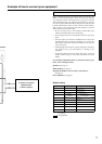

13
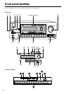
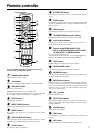
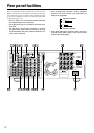
Rear panel facilities
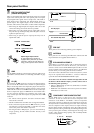
Optical digital input terminal
An optical digital input terminal is
equipped with a protection cap. When
connecting, remove this cap. When not
using, put the cap back on the terminal.
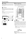
COAXIAL Coaxial cable
OPTICAL Optical fiber cable
DIGITAL INPUT/OUTPUT
(coaxial and optical)
These are the digital audio inputs and outputs. There are 2 digital
inputs with coaxial jacks and 2 with optical jacks. The inputs
accept digital audio signals from a compact disc, LD, DVD, or
other digital source component. For digital output, there is 1
optical output. The digital outputs can be connected to MD
recorders, CD recorders, DAT decks, or other similar components.
• When using the digital inputs and outputs, make sure to also
connect the analog connections whenever possible.
• When using one of the optical input or output jacks, remove
the protective cap and keep it safely. When the jack is not used,
replace the protective cap.
• When using an optical input or output jack, always use an
optical fiber cable.
GND
Use this GND terminal for connecting the ground (or earth) wire if
a turntable is connected. Refer to “Connecting a turntable” on page
18.
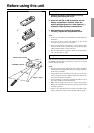
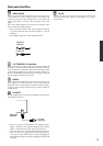
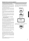
z (RI)
By connecting the z connector as shown in the diagram below,
you can use the RC-418M remote controller to operate Integra/
Onkyo cassette tape decks and compact disc players that also have
Integra/Onkyo’s z connectors. Simply connect a remote control
cable from this connector to the z connector of the cassette tape
deck or compact disc player. An z remote control cable with a
3.5-mm (1/8-inch) miniature two-conductor plug comes with
every cassette tape deck and compact disc player that has an z
connector.
• For remote control operation, the audio connection cables
must also be connected.
• The RC-418M remote controller does not support turntables.
• If the connected component has two z connectors, you can
use either one to connect to the DTR-7.1. The other one can be
used to daisy chain with another component.
• For Integra DVD or MD players, you can control them by
simply pointing the RC-418M controller directly at the
component.
REMOTE
CONTROL
Ex: CD player
Ex: cassette tape deck
DTR-7.1
z connector
z connector
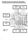
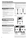
PRE OUT
These jacks are for connecting auxiliary power amplifier.
ANTENNA
These jacks are for connecting the FM indoor antenna and AM
loop antenna that are supplied with the DTR-7.1.
IR IN MAIN/IR IN ZONE 2
If the DTR-7.1 is located inside a rack or cabinet that will not
allow infrared beams to reach the IR sensor, you will need to
connect a remote sensor to IR IN MAIN input to be able to use the
remote controller. Then install the remote sensor in an unblocked
location where you can easily point the remote controller.
To use the remote controller in the remote zone (Zone 2), which
may be far separated from the DTR-7.1, connect a multiroom
system kit to the IR IN MAIN/IR IN ZONE 2 input.
To be able to use the remote controller through either the IR
IN MAIN or IR IN ZONE 2 inputs, you must connect one of
the following (sold separately):
• Onkyo’s Multi-Room System kits (IR Remote Controller
Extension System), or
• Multiroom A/V distribution and control systems from Niles
®
and Xantech
®
to name a few
COMPONENT VIDEO INPUT/OUTPUT
If your DVD player or other device has component video
connectors, be sure to connect them to these component video
connectors on the DTR-7.1. The DTR-7.1 has two component
video input connectors to obtain the color information (Y, P
B, PR)
directly from the recorded DVD signal or other video component
and one component video output connector to output it directly
into the matrix decoder of the display device. By sending the pure
DVD component video signal directly, the DVD signal forgoes the
extra processing that normally would degrade the image. The
result is vastly increased image quality, with incredibly lifelike
colors and crisp detail.
YPB PR RCA type