


17
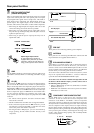
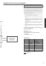
RS 232
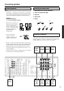
Default setting
Input source Digital input Component video
CD OPTICAL 1
PHONO ----
FM
AM
TAPE ----
DVD COAXIAL 1 INPUT 1
VIDEO 1 COAXIAL 2 ----
VIDEO 2 ---- ----
VIDEO 3 OPTICAL 2 INPUT 2
VIDEO 4 ---- ----
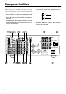
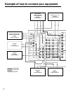
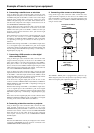
Example of how to connect your equipment
TV monitor or Projector
(MONITOR OUT)
8. Refer to page 19
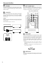
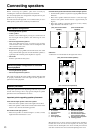
Standard connections
Here is explanation of how to connect the main components to the
DTR-7.1 in the standard manner. There are many ways that any
one component can be connected, and it is up to you to decide
which method best fits your situation. The directions given here
are only one option and should only be thought of as such. It is best
to fully understand the nature of each connector and terminal as
well as each of your components and their features to ascertain
which method of connection is best.
• Be sure to always refer to the instruction manual that came
with the component that you are connecting.
• Do not plug in the power cord until all connections have been
made.
• For input jacks, red connectors (marked R) are used for the
right channel, white connectors (marked L) are used for the
left channel, and yellow connectors (marked V) are used for
video connection.
• Insert all plugs and connectors securely. Improper connections
can result in noise, poor performance, or damage to the
equipment.
• Do not bind audio connection cables with power cords and
speaker cables. Doing so may adversely affect the sound
quality.
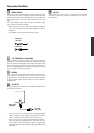
For a detailed explanation of how to connect the devices given
below, refer to the pages listed.
Speakers: See page 20
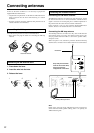
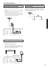
Radio antenna: See page 22
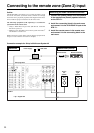
Enjoying the DTR-7.1 from a remote room (Zone 2):
See page 24
Power amplifier: See page 26
---- : No setting
: Not applicable