


12
R
R
R
L
L
L
P
B
P
R
Y
P
B
P
R
Y
P
B
P
R
Y
COMPONENT
VIDEO
REMOTE
CONTROL
PRE
OUT
R
L
(
SB
)
ANTENNA
VIDEO
1
V
IDEO
2
DVD
MON
ITOR
OUT
V
IDEO
3
R
L
INPUT 1
INPUT 2
OUTPUT
VIDEO
S VIDEO
GND
DIGITAL
OUTPUT
(
OPTICAL
)
DIGITAL
INPUT
(
OPTICAL
)
DIGITAL
INPUT
(
COAXAL
)
1
2
1
2
FRONT
SURR
SURR
BACK
SUB
WOOFER
MULTI CHANNEL
INPUT
FRONT
SURR
SURR
BACK
SUB
WOOFER
OUT
TAPE
CD
PH
R
L
VIDEO
S VIDEO
OUT
OUT
I
N
I
N
I
N
I
N
FRONT
SPEAKERS
SURR
SPEAKERS
SURR
BACK
SPEAKER
ZONE 2
SPEAKERS
CENTER
SPEAKER
CENTER
MAIN
ZONE 2
(
SB
)
CENTER
R
L
ZONE 2
MAIN
AC OUTLETS
AC 120V 60Hz
SWITCHED
TOTAL 120W 1A MAX.
IR IN
AM
IN
FM
75
R
L
ZONE
2
OUT
12 V
TRIGGER
A
B
RS 232
AC INLET
MODEL NO.
DTR-7.1
AV RECEIVER
CAUTION:
SPEAKER IMPEDANCE
6 OHMS MIN. PER EACH
SPEAKER TERMINAL
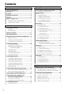
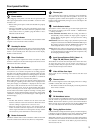
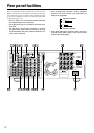
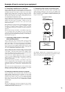
Rear panel facilities
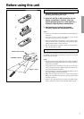
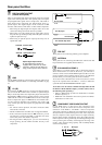
• Insert all plugs and connectors securely. Improper
connections can result in noise, poor performance, or
damage to the equipment.
Improper connection
Inserted completely
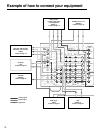
Here is an explanation of the terminals found on the rear of the
DTR-7.1 and how they are used. Before connecting your audio and
video components, be sure to read this section carefully and then
proceed to the explanations on how to connect each individual
component (see pages 16).
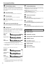
• Be sure to always refer to the instructions that came with
the component that you are connecting.
• Do not plug in the power cord until all connections have
been made.
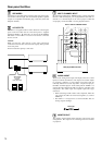
• For input jacks, red connectors (marked R) are used for
the right channel, white connectors (marked L) are used
for the left channel, and yellow connectors (marked V) are
used for video connection.
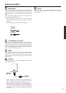
• Do not bind audio/video connection cables with power
cords and speaker cables. Doing so may adversely affect
the picture and sound quality.