


8 REAR-PANEL CONNECTIONS
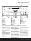
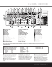
REAR-PANEL CONNECTIONS
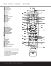
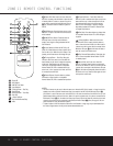
¶ Preamp Outputs: Connect these jacks to an
optional, external power amplifier for applications
where higher power is desired.
• Subwoofer Output: Connect this jack to the line-
level input of a powered subwoofer. If an external sub-
woofer amplifier is used, connect this jack to the sub-
woofer amplifier input.
ª Front Speaker Outputs: Connect these outputs
to the matching + or – terminals on your left and right
speakers. When making speaker connections always
make certain to maintain correct polarity by connecting
the color-coded (white for front left and red for front
right) (+) terminals on the AVR 330 to the red (+)
terminals on the speakers and the black (–) terminals
on the AVR 330 to the black (–) terminals on the
speakers. See page 15 for more information on
speaker polarity.
‚ Surround Back/Multiroom Speaker Outputs:
These speaker terminals are normally used to power
the surround back left/surround back right speakers
in a 7.1 channel system. However, they may also be
used to power the speakers in a second zone, which
will receive the output selected for a multiroom system.
To change the output fed to these terminals from
the default of the Surround Back speakers to the
Multiroom Output, you must change a setting in the
Advanced Menu of the OSD system. See page 31 for
more information on configuring this speaker output. In
normal surround system use, the brown and black ter-
minals are the surround back left channel positive (+)
and negative (–) connections and the tan and black
terminals are the surround back right positive (+) and
negative (–) terminals. For multiroom use, connect the
brown and black SBL terminals to the red and black
connections on the left remote zone speaker and con-
nect the tan and black SBR terminals to the red and
black terminals on the right remote zone speaker.
⁄ Surround Speaker Outputs: Connect these out-
puts to the matching + and – terminals on your sur-
round channel speakers. In conformance with the CEA
color-code specification, the blue terminal is the posi-
tive, or “+,” terminal that should be connected to the
red (+) terminal on the Surround Left speaker with
older color-coding, while the gray terminal should be
connected to the red (+) terminal on the Surround
Right speaker with the older color-coding. Connect the
black (–) terminal on the AVR to the matching black
negative (–) terminals for each surround speaker. (See
page 15 for more information on speaker polarity.)
¤ Center Speaker Output: Connect these outputs
to the matching + and – terminals on your center
channel speaker. In conformance with the CEA color-
code specification, the green terminal is the positive,
or “+,” terminal that should be connected to the red
(+) terminal on speakers with the older color-coding.
Connect the black (–) terminal on the AVR to the
black (–) terminal on your speaker. (See page 15
for more information on speaker polarity.)
‹ Video 2 Component Video Inputs: Connect the
Y/Pr/Pb component video outputs of an HDTV set-top
converter, satellite receiver or other video source
device with component video outputs to these jacks.
› DVD Component Video Inputs: Connect the
Y/Pr/Pb component video outputs of a DVD player to
these jacks.
fi Component Video Monitor Outputs: Connect
these outputs to the component video inputs of a
video projector or monitor. When a source connected
to one of the
Component Video Inputs ‹› is
selected, the signal will be sent to these jacks.
fl Fan Vents: These ventilation holes are the output
of the AVR 330’s airflow system. To ensure proper
operation of the unit and to avoid possible damage to
delicate surfaces, make certain that these holes are
not blocked and that there is at least three inches of
open space between the vent holes and any wooden
or fabric surface. It is normal for the fan to remain off
at most normal volume levels. An automatic tempera-
ture sensor turns the fan on only when it is needed.
‡ AC Power Cord: Connect the AC power cord to a
non-switched AC wall outlet.
° Switched AC Accessory Outlet: These outlets
may be used to power any device you wish to have
turned on when the AVR 330 is turned on.
· Unswitched AC Accessory Outlet: This outlet
may be used to power any AC device. The power will
remain on at this outlet regardless of whether the
AVR 330 is on or off.
NOTE: The total power consumption of all devices
connected to the accessory outlets should not exceed
100 watts.
a Optical Digital Audio Output: Connect this jack
to the optical digital input connector on a CD-R/RW,
MiniDisc or other digital recorder.
b Coaxial Digital Audio Output: Connect this jack
to the coaxial digital input of a CD-R/RW, MiniDisc or
other digital recorder.
c S-Video Monitor Output: When your television or
other video display is equipped with an S-Video input
and you are using at least one source with S-Video
capability, connect this jack to the S-Video input on
the display.
d Coaxial Digital Audio Inputs: Connect the coax
digital output from a DVD player, HDTV receiver,
LD
player
or CD player to these jacks. The signal may be a
Dolby Digital signal, DTS signal or a standard PCM digital
source. Do not connect the RF digital output of an LD
player to these jacks.
e DVD S-Video Input: Connect the S-Video output
of a DVD player or other video source to this jack.
f Video 1 S-Video Input: If the product connected to
the
Video 1 Audio Inputs has S-Video capability,
connect this jack to the PLAY/OUT S-Video jack on
that unit and then make certain that the
S-Video
Monitor Output
c is connected as described above.
g Optical Digital Audio Inputs: Connect the optical
digital output from a DVD player, HDTV receiver, LD
player or CD
player to these jacks. The signal may be a
Dolby Digital signal, a DTS signal or a standard PCM
digital source.
h Video 1 S-Video Output: If the product connect-
ed to the
Video 1 Audio Outputs has S-Video
capability, connect this jack to the REC/IN S-Video
jack on that unit.
i Video 2 S-Video Input: If the product connected to
the
Video 2 Audio Inputs has S-Video capability,
connect this jack to the PLAY/OUT S-Video jack on
that unit and then make certain that the
S-Video
Monitor Output
c is connected as described above.
j 8-Channel Direct Inputs: These jacks are used
for connection to source devices such as DVD-Audio
or SACD players with discrete analog outputs. Depending
on the source device in use, all eight jacks may be
used, though in many cases only connections to the
front left/right, center, surround left/right and LFE
(subwoofer input) jacks will be used for standard 5.1
audio signals.
k Video 2 S-Video Output: If the product connect-
ed to the
Video 2 Audio Outputs has S-Video
capability, connect this jack to the REC/IN S-Video
jack on that unit.
Video 3 S-Video Input: If the product connected to
the
Video 3 Audio Inputs has S-Video capability,
connect this jack to the PLAY/OUT S-Video jack on
that unit and then make certain that the
S-Video
Monitor Output
c is connected as described above.
Video Monitor Output: Connect this jack to the
composite video input of a TV monitor or video projec-
tor to view the on-screen menus and the output of a
standard video source.
DVD Audio/Video Inputs: Connect the composite
video and L/R analog audio output jacks of a DVD
player or other video source to these jacks.
33
32
38
31
37
36
35
34
REAR-PANEL CONNECTIONS
8 REAR-PANEL CONNECTIONS