8
Part Names and Functions
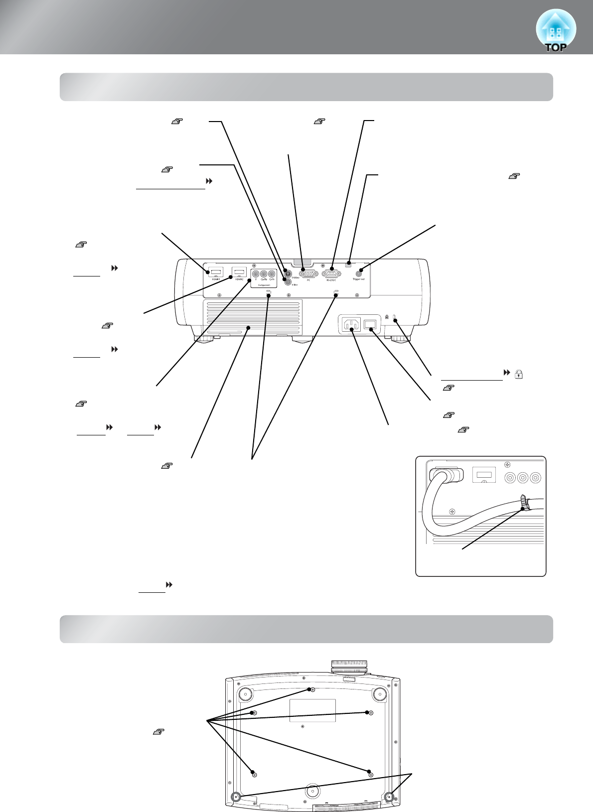
Rear
Base
• [Trigger out] port
Outputs a 12-volt DC
signal when the projector
is turned on.
It is used to transmit the
power status of this
projector (on/off) to
external equipment such
as a motorized screen.
• [Video] input port p.12
Connects to the Composite Video
output port of the video equipment.
• [HDMI1] input port*
p.12
Connects to an
HDMI
TM
-compatible
video source or to a
computer.
• [S-Video] input port p.12
Connects to the S-Video out ports
of the video equipment.
• [RS-232C] port
Connects to a computer using an RS-232C
cable to control the projector from the
computer. This is not used in normal use.
• [Power] inlet p.14
Connects the power cable.
• Main power switch
p.14
• Security lock
p.57
• [PC] input port p.12
Connects to the RGB out
port of the computer.
• [Component] input port
p.12
Connects to the component
(YCbCr
or YPbPr ) out
port of the video equipment.
• [HDMI2] input
port* p.12
Connects to an
HDMI
TM
-compatible
video source or to a
computer.
• Lamp cover open switch p.48
Press to open the lamp cover.
• Air inlet (air filter) p.45, 48
This draws in air for cooling the
inside of the projector. If dust collects
on the filter, the temperature inside
the projector will rise and problems
with operation or more rapid
deterioration of the optical
components may occur. The air filter
should be cleaned periodically.
• Cable holders
When an HDMI cable with a large outer
diameter is connected to the input port, the
weight of the cable may cause it to hang
down and result in a poor connection. To
prevent this by securing the cable, you can
pass a commercially-available cable tie
through one of the two holders whichever is
more convenient for you.
Cable tie
(commercially available)
* Compatible with HDCP
• Suspension bracket fixing
points (5 points) p.50
Install the optional ceiling mount
here when suspending the projector
from a ceiling.
• Cable cover stays
(2 places)
Attach the optional cable cover
here.


