Configuration with Communicator TroubleshootingConfiguration with ProLink IIFlowmeter Startup
Model IFT9701 Transmitter Instruction Manual 45
Chapter 7
Configuration with ProLink II Software
7.1 Configuration overview
You may use the Micro Motion ProLink II software, installed on a personal computer, to set up the
basic configuration and zero the flowmeter. See the ProLink II manual or on-line help for additional
information.
Configuration parameters include such items as flow cutoff and damping values, flow direction, and
milliamp output scaling. If requested at time of order, the meter is configured at the factory according
to customer specifications. For factory-calibrated sensors, field calibration is not normally needed nor
recommended. Basic configuration is described in Section 7.2.1.
Calibration accounts for performance variations in individual meters and peripheral devices.
Calibration procedures include autozeroing and flow calibration. Zeroing is required upon initial
flowmeter startup (see Section 4.3); flow calibration may or may not be required. For information on
calibration procedures using ProLink II, see Section 7.3.
Characterization is the process of using a communication device to enter calibration factors for flow,
density, and temperature directly into flowmeter memory, instead of performing field calibration
procedures. Calibration factors can be found on the flowmeter serial number tag and on the certificate
that is shipped with the meter. For information on characterization using ProLink II, see Section 7.4.
Set control devices for manual operation during flowmeter configuration.
CAUTION
Failure to set control devices for manual operation
during configuration will affect flowmeter
output
signals.
Before using the Configuration window, set process
control devices for manual operation.
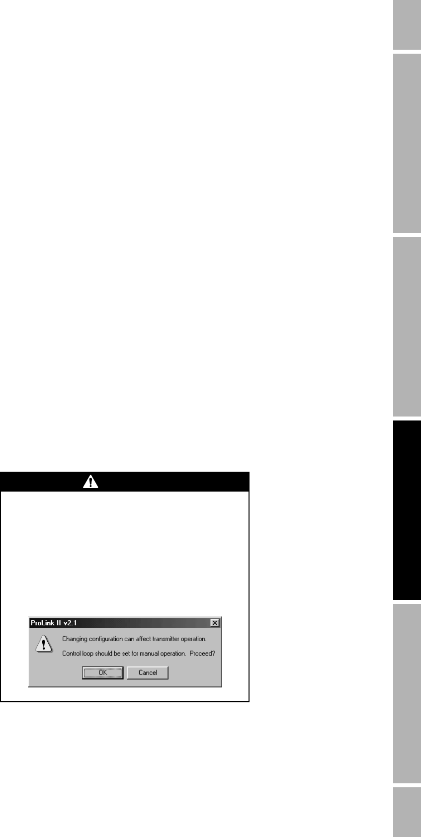
Whenever a display such as the one depicted below
appears, isolate the flowmeter from devices that use
flowmeter outputs for process control, then choose Yes.


