Model IFT9701 Transmitter Instruction Manual 21
Power Supply and Output Wiring continued
Getting Started Power Supply and Output WiringMounting the Remote TransmitterBefore You Begin
4.4 Connect output wiring
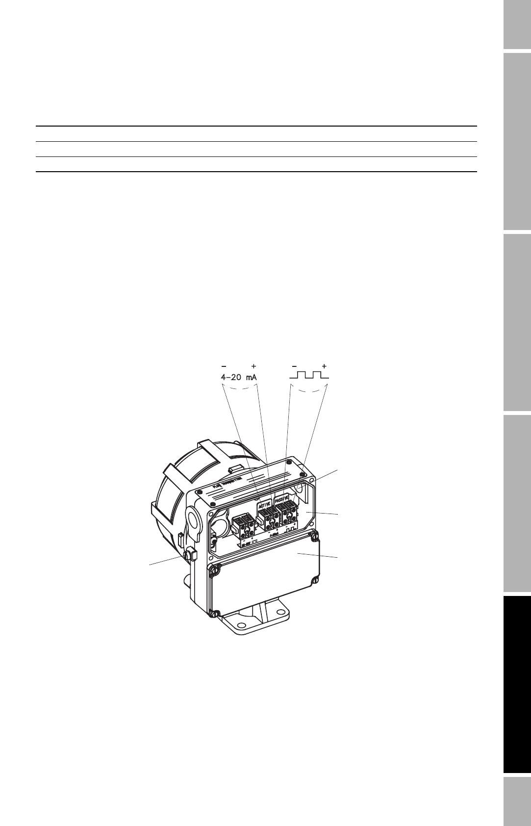
• Figure 4-2 shows the milliamp and pulse output terminals.
• Install twisted-pair, shielded cable, consisting of 20 AWG (0,5 mm²) to 16 AWG (1,5 mm²)
wire.
• For basic information on milliamp output wiring, see Section 4.4.1.
• For instructions on connecting the milliamp output to a Bell 202 multidrop network, see
Section 4.4.2.
• For instructions on connecting a HART device to the milliamp output, see Section 4.4.3.
• For instructions on pulse output wiring, see Section 4.4.4.
Figure 4-2 Output wiring terminals
Table 4-1 Wire guidelines for DC power supply
Wire size Wire length
16 AWG (1,5 mm²) 1500 feet (450 meters)
18 AWG (0,75 mm²) 1000 feet (300 meters)
20 AWG (0,5 mm²) 600 feet (200 meters)
• Terminate output cable shielding at gland or conduit fitting.
• 360° termination of shielding is not necessary.
• Do not terminate shield inside wiring compartment.
• The pull-up resistor must be of sufficient value to limit the total loop current to less
than 500 ohms. Refer to Section 4.4.4 to determine the pull-up resistor needed.
Field wiring
compartment
Sensor wiring
compartment
Case ground
Active milliamp output
Internally powered
Passive pulse output
Requires pull-up resistor
to external 5–30 VDC
power supply
Conduit opening
for output wiring


