


Introduction
7
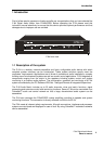
P 64 Digital Audio Matrix
Owner’s manual
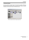
The P 64 is equipped with all relevant interfaces by default in order to provide the connection to
the network and external components. The Ethernet port makes the connection to existing
building networks (intranet) and communication via the Internet possible. Ethernet is also the
common connection between one or more P 64s and a PC with IRIS-Net software for the
configuration, control and monitoring of the P 64 System. Two RS-232 serial ports can be used in
order to control the P 64 from external multi-media systems, e.g. Crestron™ or AMX™. For that,
an open interface protocol is available. The remote CAN-bus serves as connection to
DYNACORD remote amplifiers. Up to 100 amplifiers can be attached via CAN to one single P 64.
Together with additional P 64s and amplifiers they can also be integrated in a complex and
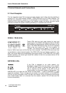
powerful audio system. The P 64 also has a control port which offers freely programmable
control inputs and outputs. Switches, potentiometers or external control voltages can be
connected to the control inputs (GPIs). Any logic and analog functions can be programmed.
External elements which can be used to signal certain states can be attached to the control
outputs (GPOs). A PC can be connected to the USB port on the front faceplate if the P 64 has
been installed in a rack and the Ethernet port cannot be reached easily. Via the USB interface the
network parameters of the P 64 can be edited and files containing the entire P 64 configuration
can be transferred.
The highest standards regarding construction and mechanical working have been followed. The
chassis is extremely robust and, therefore, effectively protects the electronics against outside
influences. A temperature controlled fan provides thermal stability and also constant ambient
conditions inside the device. All audio interfaces are electronically balanced and have Phoenix
screw terminal connectors.
By reading this instruction manual you will get to know many additional features and functions of
the P 64. Please read on attentively and keep this manual in order to be able to consult it at any
time.
1.3 Unpacking and warranty
Please open the packaging and uncase the P 64. The following accessories are added to the
device:
• P 64 owner’s manual (this document)
• Power supply cord
• 2 CAN terminating impedances
• 2 Phoenix connectors (6-pin)
• Warranty card
Please completely fill out the warranty card in the event that you need to make a warranty claim.
We also ask you to keep the sales slip and the packaging together with the warranty card in case
the unit has to be returned.