


Preparations
21
P 64 Digital Audio Matrix
Owner’s manual
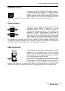
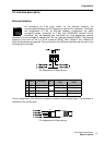
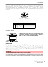
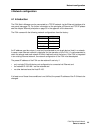
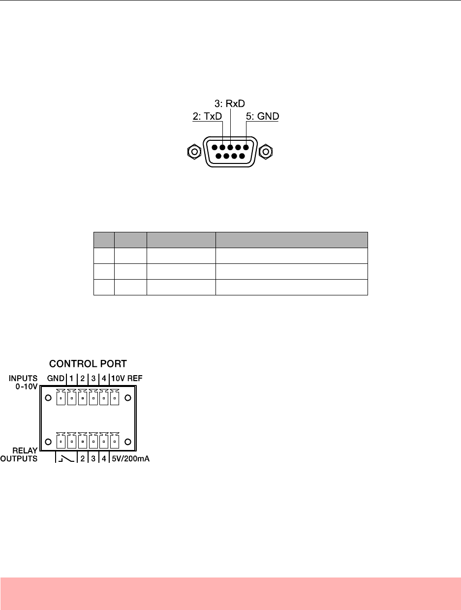
The pins of the RS-232 interface used in the P 64 are indicated in the following illustration and
table. Connections which are not given are internally connected in the P 64 so that the
communication between the P 64 and the connected device is possible via a software
handshake system. The cable which is used for the connection should not be longer than
15 meters.
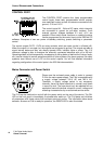
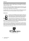
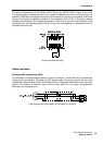
CONTROL PORT
The control port on the rear of P 64 is divided into two parts.
Two Phoenix connectors (6-pin) are included in delivery in
order to be able to connect external components.
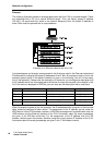
Control Inputs
The upper part, which is marked as INPUTS 0-10V on the device, provides four freely
programmable control inputs for voltages between 0 volt and 10 volts. The inputs are numbered
in order from 1 to 4. The P 64 provides its own voltage supply for externaly connected monitoring
elements, e.g. potentiometers or switches. The voltage supply is available at the 10V REF and
GND connectors of the control port.
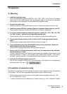
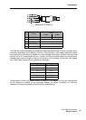
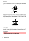
The following figure shows an example application for the "analogue circuit" on the control inputs
of the P 64. A voltage which can be changed via a potentiometer is connected at the control input
Assignment of RS-232 jack
Pin Name Description Input/Output (view from P 64)
2 TxD Transmit Out
3 RxD Receive In
5 GND Signal Ground -
ATTENTION:
The maximum allowable current at the 10 V REF is 100 mA.