


Preparations
22
P 64 Digital Audio Matrix
Owner’s manual
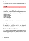
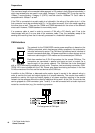
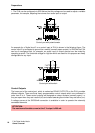
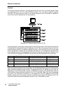
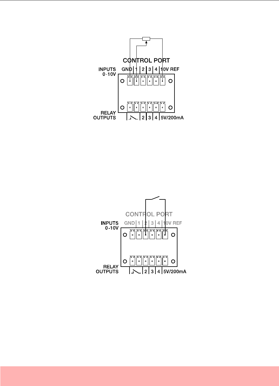
1. The P 64 can be configured via IRIS-Net so that this voltage can be used to adjust a variable
parameter, for example, adjusting the volume of an audio input or output.
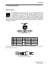
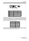
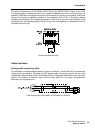
An example for a "digital circuit" on a control input of P 64 is shown in the following figure. The
control input 2 is connected to ground via a switch (normally open contact). In IRIS-Net the P 64
can be so configured that, for example, an audio input or output channel can be muted by
operating a switch. The threshold voltage for high/low which are used for this purpose are freely
configurable for any input.
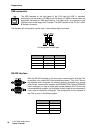
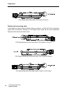
Control Outputs
The lower part of the control port, which is marked as RELAY OUTPUTS on the P 64, provides
different outputs. There are three freely programmable control outputs which are numbered in
order from 2 to 4. These control outputs are designed as relays contacts (normally open), i.e.
they are open when they are inactive (off) and closed towards ground when they are active (on).
A voltage source at the 5V/200mA connection is available in order to operate the externally
connected elements.
Control port with potentiometer
Control port with switch
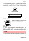
ATTENTION:
The maximum allowable current at the 5 V output is 200 mA.