


Preparations
18
P 64 Digital Audio Matrix
Owner’s manual
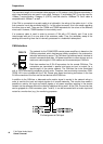
The maximum length of a connected cable segment is 100 meters in both Ethernet standards, in
which two twisted pairs are used in one cable. Category 3 (unshielded CAT-3) can be used for
10Base-T communication. Category 5 (CAT-5) must be used for 100Base-TX. Cat-5 cable is
compatible with 10Base-T as well.
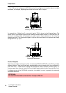
If the P 64 is connected via a patch cable to a hub/switch, the wiring of the cable at pin 1 of the
first connector has to be connected with Pin 1 of the other connector; this is the same regarding
the other pins as well. There are the T568A and T568B standards for the colors of the different
wires used. However, T568B standard is more widely-used.
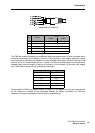
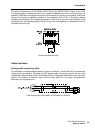
If a crossover cable is used in order to connect a P 64 with a PC directly, pair 2 has to be
interchanged with pair 3 on one side of the crossover cable. Thus, the necessary swap of the
sending and receiving lines that is internally processed in a hub/switch takes place.
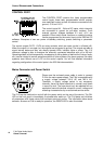
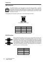
CAN Interface
The network for the DYNACORD remote power amplifiers is based on the
CAN-bus standard, which has become widely accepted in the automotive,
industrial and security sector. The CAN-bus is a balanced serial interface to
transmit commands and data. 100 power amplifiers or other devices up to a
maximum cable length of 1000 meters can be connected per CAN-bus.
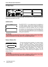
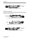
Each bus member has 2 RJ-45 connectors for the remote CAN-bus. The
connectors are connected in parallel and serve as input or output (for a
loop-through) of the remote network. The CAN-bus has to be terminated
with a 120 Ω terminating resistance at both ends. Therefore, two terminating connectors CAN-
TERM 120 Ω are included with the P 64. Please plug these terminating connectors in the free
RJ-45 connectors of the first and the last device at the CAN-bus.
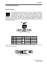
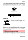
In addition to the CAN-bus, a balanced audio monitor signal is carried in the network wiring in
order to monitor the input and output signals of all remote networks. This monitor bus makes it
possible to monitor the input and output signals of all power amplifiers existing in the remote
network via the software without the need for additional wiring work. At the P 64, the monitor bus
can be gripped at a CAN connector (pins 7 and 8), it can be connected with an audio input and
routed to a monitor box (e.g.) for monitoring purposes.
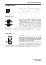
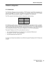
Pin Assignment of CAN jack