


Control Elements and Connections
13
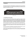
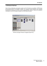
P 64 Digital Audio Matrix
Owner’s manual
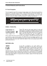
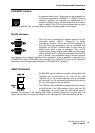
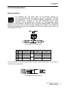
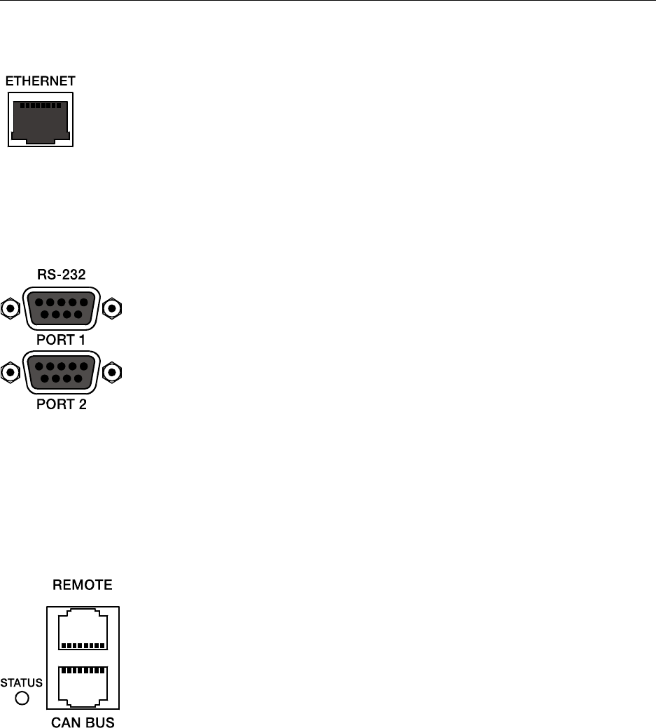
ETHERNET Interface
A computer and/or other P 64 devices can be connected via
the Ethernet interface for 100Base-TX / 10Base-T Ethernet
networks. Normally this connection is established via a
standard (straight throug) Ethernet cable and an Ethernet
hub or a switch. If the P 64 is to be connected directly with a
computer or another P 64, a crossed Ethernet cable (crossover cable) must be used.
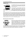
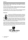
RS-232 Interfaces
The P 64 can be connected to external devices, such as
multimedia system (AMX™, Crestron™) or facility
management systems via the two RS-232 interfaces. All
P 64 functions and parameters can be controlled and
monitored via RS-232. Communication is done using an
ASCII parser which is easy to implement. Thus, a P 64
system can be easily combined with media and touch panel
control systems. A PC can also be connected to the RS-232
port to access P 64 parameters using a terminal program
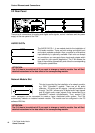
like Hyperterminal. A special instruction set is available in order to establish a connection to a
PROMATRIX
®
System DPM 4000 matrix manager. The two RS-232 ports can be configured
according to their corresponding application via the IRIS-Net PC software.
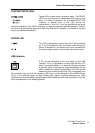
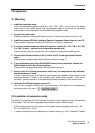
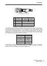
REMOTE CAN BUS
DYNACORD remote amplifiers and other devices with CAN
interfaces can be connected to the P 64 via the CAN
interface. Up to 100 remote amplifiers can be connected
with a single P 64. All connected components are linked to
the P 64 monitoring and control platform.
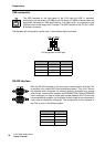
The STATUS-LED is provided to monitor the communication
on the CAN bus. If the CAN interface is not in use, the LED
is deactivated. In normal mode the LED flashes every 2
seconds. The duration of the flashing within these 2 seconds depends on the bus load. The
higher the bus load is the longer the duration of the flashing within these two seconds will be.