


-2-
B. POWER ADJUSTMENT.
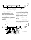
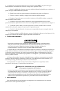
See figures 1 and 2. Multiple power settings are achieved via selection of transformer tabs. The
unit is set at the factory to the 8-watt position. To adjust the power (volume), remove the receptacle/
wire assembly for power setting and place it on the transformer tab corresponding to the desired
power (see table 1). Ensure that the receptacle is fully seated on the tab.
C. SPECIFICATIONS.
The AMR6-2570 and AMR6-100 are high fidelity 6.5" 2-way speakers, incorporating a 14mm
hard dome, neodymium tweeter.
Frequency response rating 110 Hz - 20,000 Hz
Maximum Supervisory Voltage 100Vdc
UL Audibility Rating See Table 1
Audibility Ratings On Axis
@ 10", 8-watt tap
Model AMR6-2570 81 dBa, 25 volt tap, 85.0 dBa, 70 volt tap
Model AMR6-100 85.0 dBa
Weight 3 pounds
Construction ABS Frame - UL VO, 5VA Flame Class
White Powder Coated Steel Grille
D. INSTALLATION.
To avoid electrical shock, do not attempt to install wires when power is on.
1. Electrical Connections.
FOR SUPERVISED SYSTEMS
An uninsulated section of a single conductor must NOT be looped around a terminal and
used as two separate connections. The wire must be severed to provide electrical
supervision of the connection.
Use 2 x 14-18 AWG wiring for speaker models.
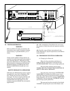
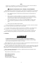
Strip 1/4" of insulation from all wiring leads. Attach the appropriate wires to the correspond-
ing terminals on the back of the speaker as shown in figures 1, 2, and 3. The positive or “+” terminal
is marked with a red screw head. Tighten the screws to ensure that the wires are firmly held in
place.
To select the desired wattage, refer to paragraph B. and see figures 1 and 2. Move the
receptacle-wire assembly to set the desired output level. See table 1.
The 25/70 volt model is factory configured for 70 Vrms operation. For 25 Vrms operation
remove the supplied receptacle/wire assembly and place it on the 25V tab (see figure 1). The 100
volt model is factory configured for 100 volt operation and no user connections are required.
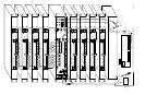
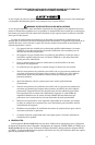
2. Mounting (see figure 4).
Both loudspeaker models are mounted using the R6BB back box and R6TB support bridge.
These loudspeakers can easily be mounted to any surface thickness between 1/4" and 1-1/2" due to
the unique adjustable “L” shaped clamps (see figure 4). Mounting of this product using the Model
R6BB back box and Model R6TB support bridge into a ceiling tile is accomplished as follows:
a. Remove the ceiling tile and cut a hole using the enclosed template or using the Model
R6TB support bridge as a template.
b. Bend up the four horseshoe tabs on the bridge (see figure 4).
c. Replace the tile and push back an adjacent tile.