


-15-
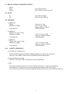
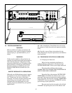
AUDIO OUT
PRESET 7
DRY CONTACT IN (N.O.)
+
ALARM
INDICATOR
-
- +
ZONE 3
PRESET 3
DRY CONTACT IN (N.O.)
- +
ZONE 1
PRESET 1
GND+24V
POWER OUT
TO PRESET
ABOVE
GND +24V
- +
ZONE 2
AUDIO OUT
PRESET 2
- +
ZONE 4
PRESET 4
- +
ZONE 5
- +
ZONE 6
PRESET 5 PRESET 6
- +
CH B INPUT
CH B INPUT
VOLUME
MICROPHONE
VOLUME
AUDIO IN FROM EXTERNAL AMP
OR FROM AUDIO OUT 15W
- +
ZONE 7
- +
ZONE 8
PRESET 8
AUDIO OUT
TO BELOW
- +
- +
ALL CALL
OPTO
COMMON
+24V
AUDIO OUT
CONTROL OUT
TO ZONE
PHONE LINE
NUMBER
( )
25Vrms
AUDIO OUT(15W)
70Vrms
- +
AUDIO OUT
1Vrms
25V
rms
70V
rms
1V
rms
25V
rms
70V
rms
1V
rms
SELECT
VOLUME
CONTROL IN
FROM PRESET
PHONE
VOLUME
CH B
- +
CH A INPUT
SELECT
CH A INPUT
VOLUME
SELECT
CH A
MONITOR
SPEAKER
VOLUME
(CLASS 2) POWER
OUT TO AR2000-P
(CLASS 2)
POWER OUT
TO AR2000-Z
CAUTION: TO REDUCE
THE RISK OF FIRE,
REPLACE ONLY WITH
BUSS 250V, 4A GMT FUSE
(CLASS 2)24VDC
BACKUP POWER
120 VAC, 50/60 HZ, 2A
240 VAC, 50/60 HZ, 1A
CAUTION: TO REDUCE THE RISK OF FIRE,
REPLACE ONLY WITH GMC 2A, 250V FUSE
WARNING:
NO USER-SERVICEABLE PARTS INSIDE. REFER SERVICING TO
QUALIFIED PERSONNEL. TO REDUCE THE RISK OF FIRE OR ELECTRICAL SHOCK,
DO NOT REMOVE COVER OR EXPOSE THIS APPLIANCE TO RAIN OR MOISTURE.
290A4120-10
B
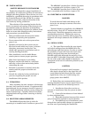
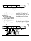
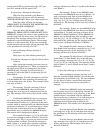
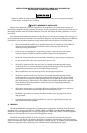
TYPICAL CONNECTION
CD PLAYER AND MODEL 300MB
RIGHT
LEFT
SPLIT OR CONNECT TO
ONLY LEFT OR RIGHT CHANNEL
CD PLAYER
17 11314110
GAIN
CENTER
TB-1
TB-2
-
+
SIGNAL
GROUND
120VAC
300MB
120VAC
SIGNAL LINES SHIELDED
TWISTED PAIR
SIGNAL LINES SHIELDED
TWISTED PAIR
Figure 3-7.
IV. TESTING/OPERATING.
WARNING
Failure to follow all safety precautions and
instructions may result in property damage,
serious injury, or possible death to you or
others.
WARNING
Under certain conditions these devices are
capable of transferring sound loud enough to
cause hearing damage. Adequate hearing
protection should be worn if standing within
close proximity to the device while testing.
Recommendations in OSHA Sound Level
Standard (29CFR 1910) should not be ex-
ceeded.
SAFETY MESSAGE TO OPERATORS
Although your Multiplexing system is operat-
ing properly it may not be completely effec-
tive. People may not hear or heed your
messages. You must recognize this fact and
ensure that your messages achieve their
intended effect through proper test and
training sequences suitable for your specific
application(s).
4-1. After completion of installation be sure to test
the system to verify that each unit operates satisfac-
torily.
4-2. Provide a copy of these instructions for the
Safety Engineer(s), System Operators(s) and Mainte-
nance personal.
4-3. TELEPHONE FUNCTION COMMANDS.
A. Changing the Password.
When the line attached to the Router is
called, the Router will answer with the message
“ENTER PASSWORD”. Enter your 8 digit password.
Then the caller will hear the message
“PRESS 9 KEY TO CHANGE THE PASSWORD OR
6 KEY TO RECORD A MESSAGE”.
Press the 9 key, the message “ENTER NEW
PASSWORD” will inform the caller to enter a new
password. The same new password must be entered
twice. The caller will hear the message “PASSWORD
CHANGED” then the message “GOODBYE” and the
system hangs up the phone line.
The password can be returned to the default
“12345678” by opening the cover of the Router and