


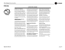

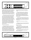
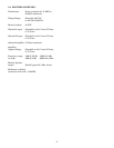
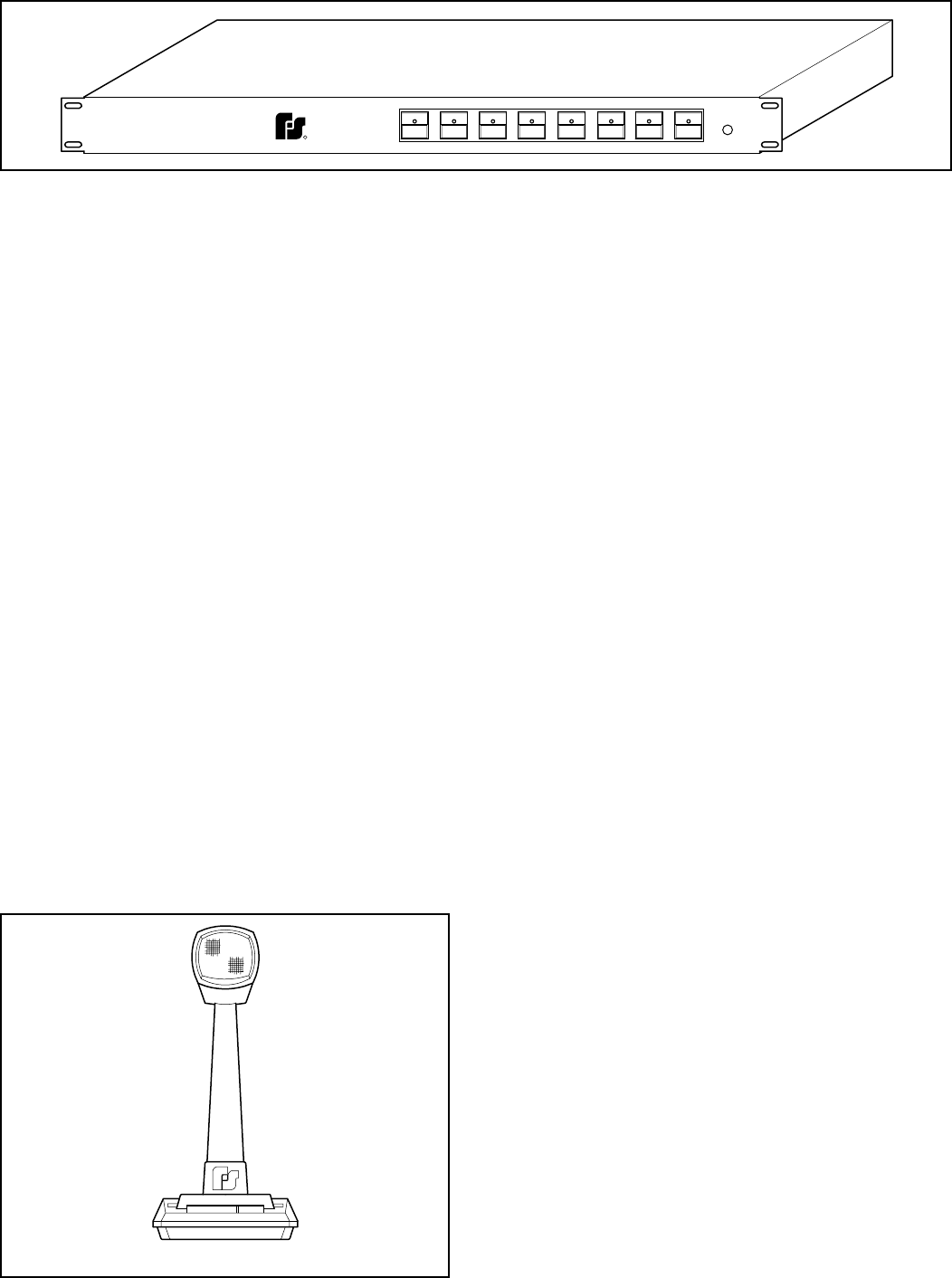
PRESET 2
AR2000-P
UNIVERSITY PARK, IL U.S.A.
CORPORATION
FEDERAL
SIGNAL
R
PRESET 1 PRESET 5PRESET 4PRESET 3 PRESET 7PRESET 6 PRESET 8
POWER
290A4120-03
Figure 1-3.
If the correct password is entered the caller will
hear the message “PRESS 9 KEY TO CHANGE THE
PASSWORD OR 6 KEY TO RECORD A MESSAGE”.
If the caller presses the 9 key, the message
“ENTER NEW PASSWORD” will inform the caller to
enter a new password. The same new password must
be entered twice. Otherwise, the caller will hear the
message “PASSWORD NOT CHANGED” then the
message “GOODBYE” and the system hangs up the
phone line. If the new password is successfully
entered twice, the caller will hear the message
“PASSWORD CHANGED” then the message
“GOODBYE” and the system hangs up the phone
line.
If the caller presses the 6 key, the message
“RECORD MESSAGE, PRESS # KEY TO BROAD-
CAST YOUR MESSAGE” prompts the caller to start
speaking. The message can be up to 90 seconds long.
If the user exceeds 90 second duration, the message
will not play back.
At any time during the call, the caller can enter
the # key or hang-up the phone to exit. Also, when a
key input is necessary, the caller has 5 seconds to
enter a key or the system hangs up automatically.
The password can be returned to the default
“12345678” by opening the cover of the Router and
setting switch SW1 position #4 to the “ON” position
for 5 seconds with the power “ON”.
Default is to all zones. Phone receiving is
disabled during message playback; therefore, subse-
quent calls must wait for the current message to be
completed before another recording will take place.
Preset operation
The preset optos are a combination of edge and
level-tripped. If the system sees an active edge on an
opto, it will set the input and output relays for the
corresponding preset. The relays will remain set
until the input goes away.
Setting a Preset:
To set a preset, select the zones desired for the
preset by pressing and releasing the appropriate zone
button. The LED corresponding to that zone will
illuminate. Select the input source (Channel A or
Channel B) for that preset. Press and hold the
appropriate preset button until it begins to flash.
The preset is now set.
To recall a preset simply select the preset by
pressing and releasing the associated preset button.
1-2. CHASSIS DESCRIPTION.
The Model AR2000-M is assembled in a black,
sprayed aluminum 3-piece housing approximately
17.5” wide by 14.25" deep by 3.5" high. It is intended
to be rack mounted in a standard 19” rack mount
cabinet.
The housing is held together with eighteen
screws, eight on the front panel, six on the rear panel
and four securing the top to the sides.
The main printed circuit board is attached to the
lower housing with seven screws. Separate wiring
harnesses connect the front and rear boards to the
main printed circuit board. The front panel switches
are designated as CH A, CH B, ALL CALL, CANCEL
ZONE 1 through ZONE 8 and PRESET 1 through
PRESET 8.
The Model AR2000-P is assembled in a black,
sprayed aluminum 3-piece housing approximately
17.5” wide by 10.125" deep by 1.75" high. It is in-
tended to be rack mounted in a standard 19” rack
mount cabinet. The housing is held together with
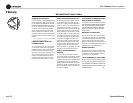
290A4120-0
4
Figure 1-4.
-3-