


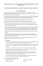

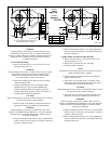
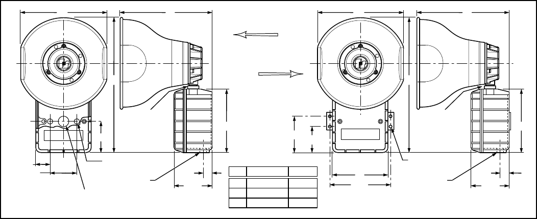
290A2627-76B
MODEL
AM302
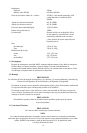
MODEL
AM302GCX
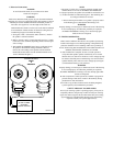
A" C"
B"
1-13/16"
.201" DIA. 2 HOLES
(MOUNTING)
2-9/16"
7/8" DIA. CONCEALED CONDUIT KNOCK OUT
MOUNTING(IN REAR OF HOUSING)
2-3/4"
COLLAR
NUT
1/2-14 NPT
5-5/8"
13/16"
3-3/8"
5-5/8"
13/16"
3-3/8"
5-1/2"
2-1/4"
3-1/4"
5"
INCHES MM
A
B
C
254
381
279
10"
15"
11"
COLLAR
NUT
B"
A" C"
.201" DIA. 4 HOLES
(MOUNTING)
1/2-14 NPT
Figure 1. Models AM302 and AM302GCX Speaker Dimensions.
WARNING
Property damage, serious injury, or death could occur if an
accumulation of water, snow, dust, etc. resides in the speaker
projector, severely reducing or preventing operation of this device.
Mount the unit so speaker projector is pointed horizontally
or slightly downward.
1. Flat Surface Mounting.
a. Remove and retain the two screws that secure cover to
housing. Remove the cover.
WARNING
Property damage, serious injury, or death could occur if any objects
are in front of speaker, severely reducing optimum sound
distribution. For maximum effectiveness, ensure that the
front of the speaker is clear of obstructions.
b. Select the mounting location and place rear of housing
against mounting surface.
c. Using the mounting holes (two (2) inside the Model
AM302’s housing or four (4) in the AM302GCX’s
external mounting bracket) as a template, scribe drill
position marks on the mounting surface. See figure 1 for
mounting hole locations and dimensions.
CAUTION
Before drilling holes in any surface, ensure that both sides of surface
are clear of items that could be damaged.
d. Secure the unit to the mounting surface with #10 screws
appropriate for the type of mounting surface material.
WARNING
Property damage, serious injury or death could occur if the
projector is mishandled during installation or over time. DO NOT
rotate the projector more than 180 degrees or internal speaker
wiring may be damaged.
e. Reposition speaker projector if necessary to obtain desired
sound coverage. Loosen collar nut (see figure 1) and move
projector to desired position.
f. Before reinstalling the housing cover, read paragraph 4 in
section C, Electrical Connections, and make the necessary
electrical connections.
2. Model AM302 Concealed Conduit Mounting.
a. Remove and retain the two screws that secure cover to
housing. Remove the cover.
b. Remove the 7/8" knockout at rear of housing.
c. Install the conduit connection.
NOTE
If installation on an existing electrical box is desired, an optional
Model CC adapter plate is required.
d. Select the mounting location and place rear of housing
against mounting surface.
e. Using the two (2) mounting holes as a template, scribe
drill position marks on the mounting surface. See figure 1
for mounting hole locations and dimensions.
CAUTION
Before drilling holes in any surface, ensure that both sides of surface
are clear of items that could be damaged.
f. Secure the unit to the mounting surface with #10 screws
appropriate for the type of mounting surface material.
WARNING
Property damage, serious injury or death could occur if the
projector is mishandled during installation or over time. DO NOT
rotate the projector more than 180 degrees or internal speaker
wiring may be damaged.
g. Reposition speaker projector if necessary to obtain desired
sound coverage. Loosen collar nut (see figure 1) and move
projector to desired position.
h. Before reinstalling the housing cover, read paragraph 4 in
section C, Electrical Connections, and make the necessary
electrical connections.