-9-
3-5. MODEL AR2000-M SIGNAL
CONNECTIONS.
CAUTION
Crosstalk can occur between signal lines and
power lines, causing confusing messages,
which interfere with the capability of this
equipment.
Do not install signal lines in the same conduit
with power lines. Avoid routing signal lines on
cable trays with high voltage power lines.
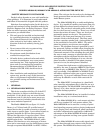
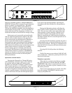
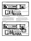
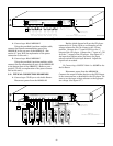
To connect the signal lines of the system to the
AR2000-M, connect a color-coded shielded twisted
pair of audio cables having conductors no smaller
than 18 AWG to + and - of each zone output being
utilized to the appropriate remote device(s). (See
figure 3-1.) Every remote signaling device in the
system will be connected in parallel to these lines.
When connecting the remote devices in parallel to the
signal lines, observe the correct polarity and install
wire nuts over the connections.
NOTE: If using the supplied amplifier or an external
amplifier, the output audio must be connected using
appropriate wire from AUDIO OUT to AUDIO IN
FROM EXTERNAL AMP. If using the on-board
amplifier, directly connect the AUDIO IN FROM
EXTERNAL AMP to the AUDIO OUT terminals on
the back of the AR2000-M. See section 3-4 for recom-
mended wire sizes.
3-6. CONNECTION TO REMOTE DEVICES.
Physically install the remote device(s); follow the
installation instructions packed with the device.
A. 300GC, 300GCX, 300X, 302GC, 302GCX,
302X, 50GC, and 50GCB.
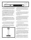
To connect these models to a 25Vrms or
70Vrms signal line, a Model AM25CK or AM70CK
connector card must be used. See figure 3-1 and
instructions below for the appropriate signal line
voltage.
B. 70 Vrms Signal Line Application.
The AR2000-M has provision for connecting
70 Vrms line operated speakers to its output. Connect
the 70 Vrms line at the terminals of Zone 1 – Zone 8
terminal block(s). Connect the speakers in parallel to
this line using 70 Vrms line tap. This output is
selected by setting the switch on the back of the
AR2000-M to the 70 Vrms position. The output audio
must be connected using 16GA wire from AUDIO
OUT to AUDIO IN FROM EXTERNAL AMP. The
Gain may be adjusted using the AUDIO OUT VOL-
UME control knob.
C. 25 Vrms Signal Line Application.
The AR2000-M has provision for connecting
25 Vrms line operated speakers to its output. Connect
the 25 Vrms line at the terminals of Zone 1 – Zone 8
terminal block(s). Connect the speakers in parallel to
this line using 25 Vrms line tap. This output is
selected by setting the switch on the back of the
AR2000-M to the 25 Vrms position. The output audio
must be connected using 16GA wire from AUDIO
OUT to AUDIO IN FROM EXTERNAL AMP. The
Gain may be adjusted using the AUDIO OUT VOL-
UME control knob.
D. Low Level Audio Output.
The AR2000-M also has provision for 1 volt
audio output that can be switched to each zone for
individual external amplification. This low level
output is available at the same terminals as in B and
C above. This output is selected by setting the
switch on the back of the AR2000-M to the 1 Vrms
position. The output audio must also be connected
using 18-20GA wire from AUDIO OUT to AUDIO IN
FROM EXTERNAL AMP. The Gain may be adjusted
using the AUDIO OUT VOLUME control knob. It
can also be connected to an analog fiber optic trans-
mitter so that audio can be transmitted over a fiber
optic link in an electrically noisy environment.
E. External Amplifier Connection for Alternate
Power Audio Output.
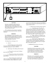
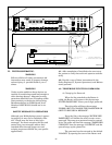
The AR2000-M also has provision to connect
an external amplifier, such as the Federal Signal
HP440,to be switched to the corresponding zones.
Set the Audio Router up as listed in D above. Con-
nect the 1 volt AUDIO OUT to the audio input of
another amplifier. The output audio must be con-
nected using appropriate wire gauge for the applica-
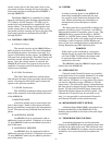
tion to the AUDIO IN FROM EXTERNAL AMP (See
figure 3-2.) The Gain may be adjusted using the
AUDIO OUT VOLUME control knob.
CAUTION
Careful attention should be paid in order to
make sure orientation of the signal is not
reversed.


