


C.Electrical Connections.
DANGER
To avoid electrical shock, do not connect wires when
circuits are energized.
WARNING
Audio wires should be sized properly by your licensed installation
electrician for your service application. This cable requires a twisted
shielded pair with an 18AWG minimum and should produce no
more than 15% signal loss over the length of the cable run.
National Electrical Code as well as local codes must be adhered
to in installation of these models. All electrical wiring must be
routed through approved conduit and fittings.
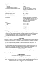
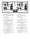
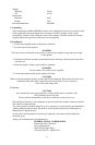
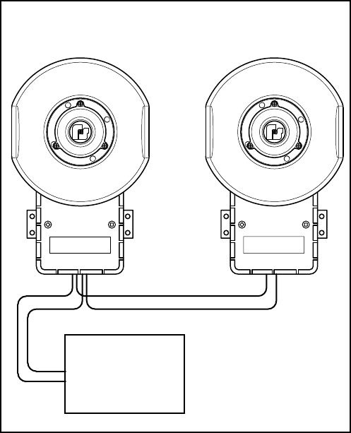
1. See figures 2 and 3. Connect the audio common (-) leads to
the speaker’s common terminal.
2. Refer to figures 2 and 3. Connect the audio positive (+) leads
to the 25V or 70V terminal, depending on the external signal
source voltage.
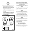
3. The AM302 and AM302GCX are factory configured for 30
W operation. If a different wattage terminal is desired,
remove the wire leading to the speaker from the terminal
marked 30 W and connect it to the terminal marked 7 W or
15 W as indicated in figure 3.
NOTE
Only three (3) of the five (5) wattage terminals marked on the
terminal block are for use on the AM302 and AM302GCX.
For proper operation, the speaker wire should be connected to one
(1) of these terminals as indicated in figure 3. The remaining two
(2) wattage terminals are not used.
4. Be sure the neoprene rubber cover gasket is properly seated
in the housing groove and reinstall the housing cover.
WARNING
Property damage, serious injury or death could occur if the housing
is not closed properly. To reduce the possibility of explosion,
the Model AM302GCX’s housing cover must be kept tight
while circuits are energized.
IV. TESTING/OPERATING.
WARNING
Under certain conditions these devices are capable of producing
sounds loud enough to cause hearing damage. Adequate hearing
protection should be worn if standing within close proximity to
device while testing. Recommendations in the OSHA Sound Level
Standard (29 CFR 1910) should not be exceeded.
A.After installation is complete, be sure to test the system to
verify that each speaker operates satisfactorily. If it is found
that the unit is too loud for its location, a lower wattage tap may
be selected. Carefully remove the housing cover and move the
speaker internal yellow lead to a lower wattage tap (see Figure
3). Reinstall the housing cover and retest.
WARNING
Property damage, serious injury or death could occur if the housing
is not closed properly. To reduce the possibility of explosion,
the Model AM302GCX’s housing cover must be kept tight while
circuits are energized.
B.After completion of initial system test, establish a program for
periodic testing of this device. Refer to the authority having
jurisdiction for this information.
C.Provide a copy of these instructions for the Safety Engineer,
system operator(s) and maintenance personnel.
SAFETY MESSAGE TO OPERATORS
Even if your warning system is operating properly, it may not be
completely effective. People may not hear or heed your warning
signal. You must recognize this fact and ensure that your warning
signal achieves its intended effect through proper test/training
sequences within your specific application(s).
290A2627-75
C
SPEAKER MODELS
AM302
&
AM302GCX
RED
BLK
25 OR 70 VRMS
SPEAKER
SIGNAL SOURCE
RED
BLK
RED
BLK
++ +
-- -
Figure 2. Typical Installation Wiring.