


-12-
WARNING
If this unit is to be connected to a non-power
limited 24 volt dc supply, the National Electri-
cal Code (NFPA70) requires that those leads
be separated from other classes of wiring
connected to this unit.
CAUTION
Cross talk, interference, or hum can be
induced in signal lines, causing poor audio
output or confusing messages, which inter-
feres with the capability of this equipment.
Do not install power lines in the same conduit
as signal lines.
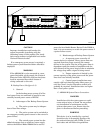
Operating power is connected to AR2000-M
by merely inserting the plug end of the line cord into
any standard 120 volt, 60 Hz outlet. The AR2000-M is
factory set for 120VAC 50/60Hz operation. If 240 volt
operation is preferred, the input block provides a
switch that must be set to this position in order to
function at 240 VAC operation.
If it is desired to use 24 VDC either as a
primary or auxiliary source of power, connect the “+”
terminal of 24 volt DC power supply to the “+”
terminal at the 24VDC BACKUP POWER terminal
on the AR2000-M and “-” terminal of the 24 VDC
power supply to the “-“ terminal at the 24VDC
BACKUP POWER terminal on the AR2000-M located
in the back of the device. (See figure 3-3.)
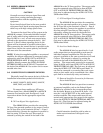
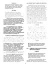
D. AR2000-P and AR2000-Z Power Connections.
Operating power is connected to AR2000-P
and AR2000-Z by merely connecting 24 VDC from the
AR2000-M to each unit. A terminal block is provided
at the rear-left side of each unit for power connection.
Observe and maintain proper polarity when wiring
the power to these units. Connect the “+” terminal of
the AR2000-M to the “+” terminal of the AR2000-P at
the “+” terminal located in the back of device. Con-
nect the “-” terminal of the AR2000-M to the “-”
terminal of the AR2000-P at the “-” terminal located
in the back of device. An additional 24VDC power
outlet is provided on each AR2000-P and AR2000-Z
for daisy-chaining the power to each sub-unit. Re-
peat for each AR2000-P and AR2000-Z.
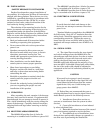
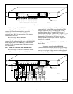
Setup for the AR2000-P presets is done in the
same way as the AR2000-M presets. (See figure 3-4.)
Setup for the AR2000-Z zones is done in the
same way as the AR2000-M. An audio input is
provided on each unit to be routed to each of the
zones it selects. This audio should be connected by
wiring a connection from the master audio output to
the provided input terminals. (See figure 3-5.) Each
additional AR2000-Z should obtain audio in the same
manner from the unit above. (See figure 3-5.)
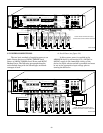
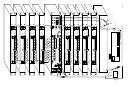
3-8. CONNECTIONS TO REMOTE SWITCHES.
The AR2000-M presets can be activated re-
motely by any normally open low current switch
contacts having a current capacity of at least 50 mA
inductive. Figure 3-6 illustrates the connection of
switch contacts to the AR2000-M. S1, S2, S3 and S4
represents remote switch contacts such as those
found in flow switches, program clocks, heat detec-
tors, and smoke detectors. The remotely activated
presets function as long as the activating contacts
remain closed. A jumper needs to be placed across
OPTO COMMON and the provided +24V terminal
next to it on the back of the AR2000-M in order for
the remotely activated presets to function. A remote
switch may be connected to the ALL CALL position if
desired. These are all Normally Open contacts that
initiate with contact closure and remain active until
the contact is opened again.
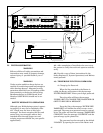
3-9. INPUT SOURCE CONNECTIONS.
WARNING
Installation or maintenance on AR2000-M
when power is on can result in serious injury
or death. Do not perform any installation or
maintenance to the system when power is on.
Set selector for CH A to the appropriate input
voltage, 1Vrms, 25Vrms or 70Vrms. Connect the “+”
of the source device to the “+” terminal at the Chan-
nel A input. Connect the “-“ of the source device to
the “-“ terminal at the Channel A input. Repeat this
process for the Channel B input. CH A and CH B
volume controls are available just above each input
selector to allow the input gain to be adjusted.
CAUTION
Be certain to set the input selector switch to
the appropriate input voltage to avoid dam-
age to the unit and the device being con-
nected.
3-10. COMMUNICATION CONNECTIONS for
AR2000-P and AR2000-Z.
WARNING
It is important that the communication lines
be properly connected to their respective
communication port. Failure to connect the
cables properly will damage the devices and
possibly render them inoperable.
The label on the back of each device indicates
where the communication cable link should be
connected. See figure 3-6 for appropriate placement.