


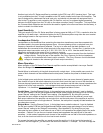
Rev 04.08.021 - 21 –
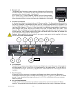
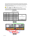
and CV2 terminals. If you wish to control both channels simultaneously, using the remote control as a master
level control and the front panel level controls as balance adjustments, both control inputs may be connected
together and driven off the wiper of a single pot. (See figure 15) An example of this application would be in a
system where the CV Series amplifier is being used to reproduce stereo information, and keeping two level
controls synchronized during adjustment would be difficult.
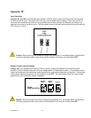
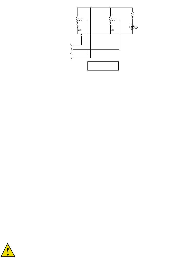
D1
RED
330
R3
"Amp On
"
"CH2 Level""CH1 Level"
R2
5kC
R1
5kC
RTN
C1
C2
+5V
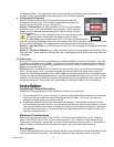
Connect the remaining terminal of the pot (full counter-clockwise position) to the +5V terminal of the “Remote
Level” input connector.
This connection will set the control voltage to 0V with the pot rotated fully clockwise (sets maximum level), 5V with
the pot rotated fully counter-clockwise (sets minimum level), and allow smooth variation between these extremes.
The VCA (voltage controlled amplifier) within the CV Series amplifier uses control information from the “Remote
Level” input terminals in the flowing manner:
1) A 0V control voltage corresponds to 0dB added attenuation (added to the attenuation already set by the
front panel Level control for that channel).
2) A 5V control voltage corresponds to 100dB added attenuation.
3) The control voltage effect is “dB linear”; a 2.5V control voltage input will add 50dB of attenuation.
4) The control characteristic is –1dB per 50mV of control voltage.
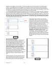
As an added bonus, low current loads, such as an LED, may be connected between the +5V and RTN terminals.
This may be useful if one desires a visual indication that the CV Series amplifier is powered ON. The +5V at the
“Remote Level” terminals turns on and off with the amplifier. (See figure 16)
Wiring Requirements for Remote Level Control Applications
For best results, use 24AWG or larger control wiring, especially for the +5V and RTN connections. Since 24AWG
wire has DC resistance of 25m per foot, using 1000 feet of 24AWG (loop resistance of 50 total) to make
connection to a 5k potentiometer will result in a 1% voltage drop, which causes a reduction in control
voltage range. This voltage drop increases as more current is carried by the +5V and RTN conductors,
i.e. when the 5V line is used to light a remote LED indicating that the amp is ON. In the (extreme) example given
above, an additional 10mA load on the +5V and RTN conductors will cause 10% reduction in control voltage
range, yielding lower maximum level and higher minimum level. Within reason, conductor capacitance is not a
problem since the control voltages are averaged in the amplifier and any additional RC delay will not be
noticeable.
Note: do not connect the RTN conductor to a ground reference at the remote control location.
Ground potential differences will drive currents through the RTN line and cause unpredictable
remote level control performance.
Fi
g
ure 16