


Rev 04.08.021 - 20 –
Figure 13
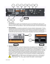
Using Other Amplifiers in the Power Sequence
The Carver pm700, pm950, pm1400, pt1800 and pt 2400 can be use together with the CV Series amplifiers in a
“Sequenced” configuration. However, as the Sequence Terminal on the pm Series has no Chassis Ground
connector, whenever this manual references the chassis ground connector you should replace it with some
reliable ground connection point on the PM series amplifier chassis such as a screw that is used in fastening the
chassis parts together. A good example would be the screws that retain the input modules to the amplifier
chassis.
All other connections would be exactly as described in this discussion of sequencing hook-up procedures.
For
operational details regarding the Carver pm Series and pt Series amplifiers, please consult their respective
user guides provide with the amplifiers.
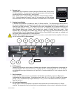
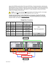
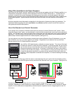
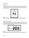
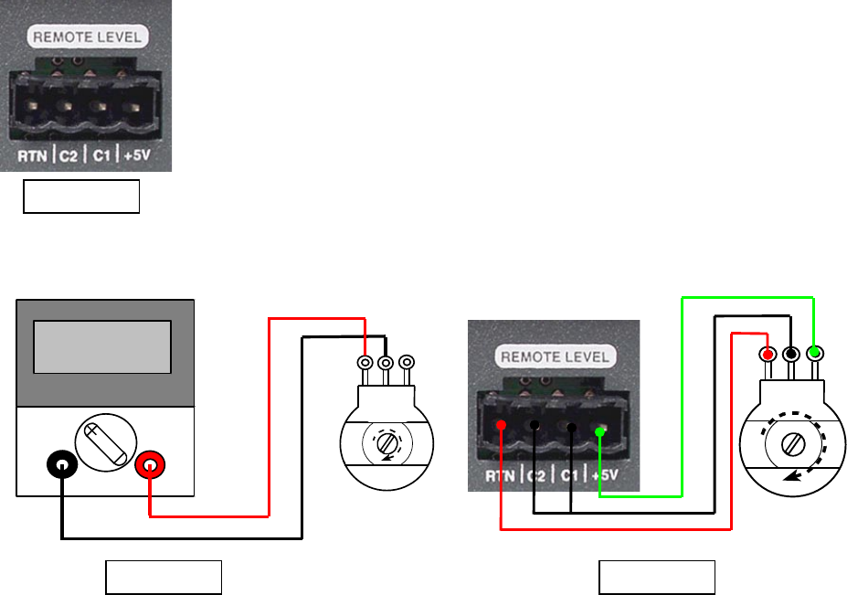
Use of the Remote Level Control Connector
A four position Euro connector furnishes contact points for the use of several “Remote Level” options. When
using the “Remote Level” option, you should keep in mind that the front panel level controls act as a master level
control. The “Remote Level” control will perform as an attenuator from the preset level set by the front panel level
adjustment. Once the master level has been set the front panel level control knob(s) may be replaced with the
plastic snap-in buttons supplied with the CV Series amplifier. (See figure 13)
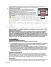
You may choose to use one of the accessory remote level controls offered by Carver Professional, or you may
elect to fashion your own in a custom panel of your design. Regardless of your decision the way that these
devices connect to the CV Series amplifier is the same.
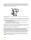
Use a 5k to 10k potentiometer, preferably a reverse log taper. The nature of the taper
will define the manner in which the control responds. A reverse log taper will give you the
type of action that you would normally expect when adjusting the level of a radio or other
conventional electronic audio device. In contrast, a linear taper will seem to have little or
no effect in the first half of its rotation. This is because it is varying at a linear rate, and at
or near full attenuation the effect is not notice until you achieve a level that is within the
sensitivity of the loudspeaker connected to the amplifier, or at least exceeding the existing
noise floor.
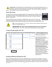
Identify the terminal of the pot to which the wiper is connected when the pot is set to the fully clockwise position.
Connect this terminal to the RTN (ground return) terminal of the “Remote Level” input connector.
(See figure 14)
0.5
Ω
Ω
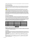
Connect the center terminal of the pot to CV1 or CV2 (control voltage terminal) of the “Remote Level” input
connector, depending on which channel you intend to adjust remotely. In the case of a dual channel CV Series
amplifier, the two channels are independently controlled by their respective control voltages applied to the CV1
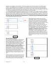
Figure 14 Figure 15