


Rev 04.08.021 - 16 –
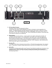
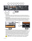
Another input to the CV Series amplifiers is provided via the EFX Loop’s RCV (receive) input. This input
is only available when the FX Loop is enabled on the DIP switch located on the rear of the amplifier. This
input is designed for unbalanced line level input only, and should only be used with equipment that is
local to the CV amplifier or rack containing the CV amplifier, such as, an outboard signal processing
device or the SND output from the FX Loop on the same or another (local) CV amplifier. This input offers
low Common Mode Rejection and should not be used for signals from units more than a few feet away, in
order to maintain low noise levels.
Input Sensitivity
The input sensitivity of the CV Series amplifiers is factory preset at 0dBu or 0.775V
rms
needed to drive the
amplifier to full rated output. Individual modules for the CV Series amplifiers may allow the user to select
other settings based on the input source. (See Appendix B)
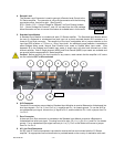
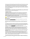
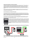
Loudspeaker Polarity
Loudspeakers or the distributed lines containing the step-down transformers must be connected with
consistent polarity for correct phasing between them. Incorrect phasing will do no physical harm, but
frequency response will be adversely affected. The key is to make sure that both speakers, or all
transformers are connected to the output terminals in the same manner. Connect the (+) positive to the
appropriate output connection such as 4, 8, 25V, 35V, 50V, 70V or 100V. Next be certain that the (-)
negative is connected to the correct (Com) or common terminal.
(Note! The low impedance 4 and 8 ohm outputs have a separate common terminal from the distributed
voltage outputs. Facing the rear of the amplifier, the (Com) Common for the low impedance
outputs is on the extreme left of each output connector. The (Com) Common for the distributed
voltages is located on the extreme right of each output connector.)
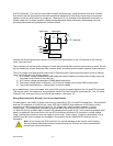
Mono Operation
Mono operation of the CV Series Dual Channel amplifiers can be accomplished in two ways: Parallel
Mono and Bridged Mono.
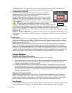
Parallel Mono is achieved by driving both channels with a single input. In the parallel mono mode, the
power of both channels can be considered as the total power, however the power is divided into two
zones.
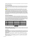
In the bridged mono mode the two channels are combined to form one mono channel of greater power.
One channel of input is fed to both channels via a circuit that inverts the input to one of the channels so
that one channel reproduces the positive half of the input waveform and the other channel reproduces the
negative half of the input waveform. In the bridged mode each channel sees one half of the total
impedance. It is, therefore, not recommended
to use a bridged load below 8 ohms.
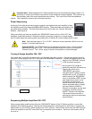
Parallel Mono – Use the Channel 2 input. In the parallel mono mode the channel 1 input is disabled.
On the input module PCB find the Bridged/Normal/Parallel mode jumpers and change it from its factory
preset “Normal” setting to the “Parallel” mono setting. (See Appendix B) By doing this you have
instructed the input module to send the channel 2 input to both channels to be used as a mono input.
Both output channels of the amplifier use a single input, and the total power of the amplifier is equal to
twice the maximum output of a single channel. However, the total power is equally divided between the
two channels or zones.
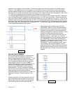
Bridged Mono - Use the Channel 2 input. In the bridged mono mode the channel 1 input is disabled.
On the input module PCB find the Bridged/Normal/Parallel mode jumper and change it from its factory
preset “Normal” setting to the “Bridged” mono setting. (See Appendix B) By doing this you have
instructed the input module to invert channel one so that it now represents the negative half of the audio
waveform. Channel 2 is now the non-inverted channel and represents the positive half of the audio
waveform. In this mode of operation each channel of the amplifier see one half of the total impedance, so
that, an 8 ohm load now looks like a 4 ohm load to each channel.
To connect the load to the amplifier you would connect the positive (+) of the load to the terminal of
channel 2 and the negative (-) of the load to the terminal of channel 1. Example: You wish to bridge the