


Rev 04.08.021 - 10 –
C
ONTROLS
A
ND
F
UNCTIONS
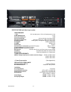
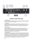
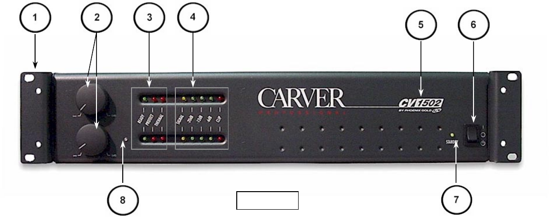
1. Rack Mount Ears
The ears for rack mounting the CV Series amplifiers are removable. If your installation does not require rack
mounting, the rack ears can be removed, however the screws that fasten the rack ears to the chassis should
be replaced to maintain the chassis’ structural integrity.
2. Level Controls
The Level Controls on the CV Series amplifiers utilize a DC voltage to control the output level of the CV
Series amplifiers through a VCA (voltage controlled amplifier). The knobs can be removed and replaced with
black plastic caps provided with the amplifier. Before installation of the plastic caps, be sure to set the
maximum level that you will need for each channel or zone. Once the caps have been installed they are
difficult to remove.
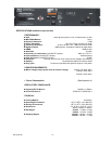
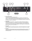
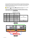
3. Status LED Display
The READY (Green LED) indicates that the power-up process has completed, and the amplifier is
operational. PROTECT (Red LED) indicates that the CV Series amplifier has detected a fault (over-current,
over-voltage or short circuit, and has placed itself into a protect mode. Check all connections and level
settings for a problem. THERMAL (Red LED) indicates that the CV Series amplifier has exceeded the
maximum allowable operating temperature. The CV Series amplifier will restart as soon as the power
transformer or heat sink has reached a safe operating temperature.
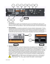
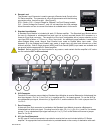
4. Level Display LEDs
Five LEDs per channel or zone, display the signal level of the CV Series amplifier. SIGNAL LED indicates
there is signal at the input of that channel or zone. The -20dB LED indicates a signal at the output of 20dB
below rated output. The –12dB LED indicates a signal at the output of 12db below rated output. The –6dB
LED indicates a signal at the output of 6dB below rated output. The CLIP LED indicates a signal at the output
that exceeds the rated output of the amplifier.
NOTE: It is normal to operate the CV Series amplifier so that
the CLIP LED illuminates (Red) at the loudest peaks of the information being reproduced. If the Clip LED is
staying on continuously, or for extended rather than momentary intervals, levels in that channel or zone
should be reduced to avoid driving the amplifier into over-voltage or over-current conditions.
Figure 1