


Rev 04.08.021 - 14 –
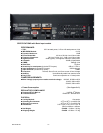
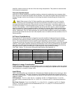
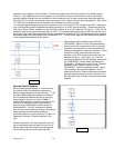
Figure 7
CV Series amplifier. If your application requires rack mounting, optional line cords, shorter than the
standard 2 meter, are available as accessory item for the CV Series amplifiers.
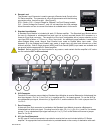
9. Configuration DIP Switches
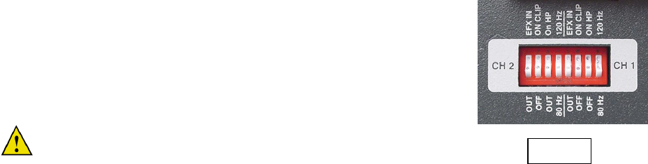
Each CV Amplifier channel can be individually configured via the DIP
Switches on the rear panel. The switches for each channel perform the
following functions from left to right:
(See figure 7)
Switch 1 - Effects In/Out (up is IN and down is OUT) this switch enables
the receive pins (+ and -) on the Effects Loop connector. When using the
Effects Loop for outboard signal processing this switch must be in the UP
(EFX IN) position.
Note: If the EFX Loop is switched (IN) with no signal present at the
EFX receive inputs, the amplifier will appear to not be working
Switch 2 – Clip Limiter (up is ON and down is OFF) The Clip Limiter prevents the
amplifier from being accidentally driven into hard clipping under normal operation. (Note: The Clip Limiter
will not protect the amplifier from clipped signals that are introduced at the amplifier input.)
Switch 3 – High Pass Filter (up is ON and down is OFF) This switch engages or disengages the internal
High Pass filter.
Switch 4 – Frequency Selection (up is 120Hz and down is 80Hz) this switch selects the frequency of the
High Pass filter. (Note: whenever the High Pass filter is disengaged a 26Hz
factory preset
high pass filter
is engaged)
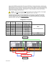
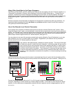
10. Effects Loop
A four pin Euro Style connector is provided for an unbalanced Effects Loop send and receive. The Input
Overload of this feature is set at 20dBu. This Effects Loop can be used to send and receive unbalanced
signals from outboard signal processing equipment such as EQ’s, Delays, Limiters and others. For the
Effects Loop receive signal, the
EFX IN Switch on the configuration DIP Switch must be set to the (IN or up) position for that channel or
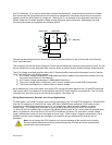
zone. The Send pins (+ and -) are always engaged and can be used to loop signal from one amp to
another via the receiving amplifiers input module. (Note: The signal at the Send Pins of the Effects Loop
are post any signal processing performed by a optional input module that may be in use in the CV Series
amplifier). Connections to the Effects Loop are intended to be local, and signals sent over long wire runs
are not recommended. Input through the “Input Module” would perform better in this circumstance.
Installation
Location and General Precaution
Observe the following precautions when choosing a location for your amplifier.
A. Do not expose the unit to rain or moisture. If a fluid or foreign object should enter the unit, disconnect
the power plug and contact the Carver Professional Service Center. Do not pull out the plug by
pulling on the cord; grasp the plug firmly and pull.
B. Protect the amplifier from heat, and allow adequate ventilation. Place away from sources of heat,
such as heating vents and radiators. All components produce some heat during operation, so make
sure that the ventilation area above and below the heatsink are not covered and that air is allowed to
circulate freely around the unit. Excessive heat is the single greatest source of both short-term and
long-term component failure.
Mechanical Considerations
When being rack mounted, the CV1501, CV2501, CV1502 and the CV2502 are 2U or 3.5” (89mm) in
height, The CV4002 is 3U or 5.25” (133mm) and they are all 17.25” (438mm) in depth inside the rack
including the rear supports. Secure the unit to the rack mechanically using four screws. The addition of
plastic or rubber washers prevents marring the front panel, but may interfere with grounding.
Rear Support
If the CV Series amplifiers are rack mounted and the rack is to be transported, mechanical support for the
rear of the amplifier(s) is required. This could take the form of any mechanical means of tying the