


Rev 04.08.021 - 15 –
amplifier’s chassis structure to the rear of the rack during transportation. This practice is recommended
for all electronic components.
Thermal Considerations
When the CV Series amplifiers are used free standing, no thermal considerations are necessary other
than using the four rubber feet supplied with the amplifier. This raises the amplifier above the surface it is
sitting on enough to allow free movement of air through the heatsink located along the left side of the
amplifier.
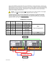
Note! When several of the CV Series amplifiers are mounted together in a rack, it may be
necessary to provide openings at both the top and bottom of the rack to allow convection to
exchange the heated air at the top of the rack with cool air from the bottom. A minimum space of 1U
should be left between CV Series amplifiers at no more than a 12U interval. This should allow sufficient
cooling of the amplifiers. If the CV Series amplifiers are mixed with other devices, caution should be
taken to locate the CV Series amplifiers together, facilitating the chimney effect of their heatsink design.
Space should be left above and below the CV Series product, grouped together in the rack, for proper
airflow. Additionally, if the CV Series amplifiers are used with other amplifiers, caution must be taken to
ensure the heat forced into the rack from other amplifiers does not interfere with the ventilation of the CV
Series amplifiers.
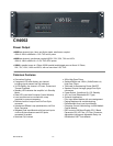
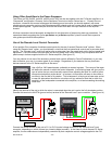
AC Power Considerations
Ensure that the CV Series amplifier is plugged into an outlet capable of supplying the correct voltage
specified for the model and enough current to allow full-power operation of all the amplifiers utilizing that
circuit. The current demand of a power amplifier varies depending on several factors, including the
impedance of the load, the output level of the amplifier, and the crest factor and duty cycle of the program
material. Under typical conditions reproducing contemporary music, with all channels driven into a four-
ohm load to the point where the peaks are just at the clipping point, the amplifiers require the following
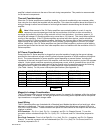
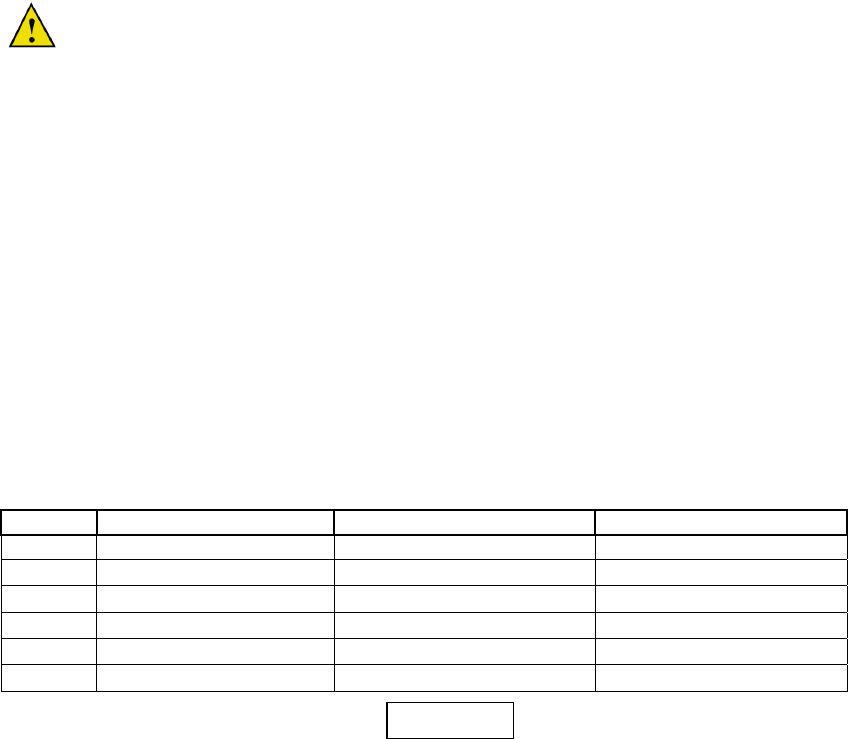
average currents: Psuedo Pink Noise @ 1/3 rated power into 4 ohm autoformer winding.
(See Table 1 below) For full power consumption specifications (See Appendix A)
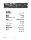
Model 100VAC (50/60 Hz) 120VAC (60Hz) 230VAC (50Hz)
CV1501 101 Watts / 1.35 Amps 101 Watts / 1.13 Amps 101 Watts / 588 mA
CV2501 148 Watts / 2.06 Amps 153 Watts / 1.75 Amps 153 Watts / 1.09 Amps
CV1502 172 Watts / 2.35 Amps 180 Watts / 1.89 Amps 179 Watts /1.28 Amps
CV2502 285 Watts / 3.7 Amps 308 Watts / 3.3 Amps 289 Watts / 1.69 Amps
CV4002 448 Watts / 4.92 Amps
Magnetic Leakage Consideration
The CV Series amplifiers may be mounted without concern for magnetic flux leakage, within the confines
of common sense. For example, it is not good practice to mount any power amplifier near a microphone
input transformer or magnetic storage media.
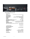
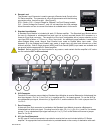
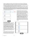
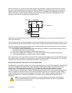
Input Wiring
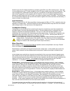
The CV Series amplifiers are furnished with a Standard Input Module that allows a line level input, either
balanced or unbalanced. The input connectors on the Standard Input Module are a female XLR and a
3-pin Euro Style connector. These connectors are paired for each channel of the amplifier and are wired
together in parallel.
XLR Connector – Pin 2 is + (hot), Pin 3 is – (negative), and Pin 1 is Chassis Ground. To use this
connector with an unbalanced input Pin 2 is + (hot), Pin 1 is Ground, and Pin 3 should be jumpered to
Pin 1.
Euro Style Connector- From Left to Right Pin 1 is + (hot), Pin 2 is – (negative), and Pin 3 is Chassis
Ground. To use this connector with an unbalanced input; Pin 1 is + (hot), Pin 3 is Ground, and Pin 2
should be jumpered to Pin 3.
Table 1