


Installation & Operations Manual
CR-25E Cable Beam Barrier Installation, Adjustment & Maintenance 5 of 31
© 2007 B&B ARMR WWW.BB-ARMR.COM (800) 367-0387
NOTE: This barrier has been completely assembled and test run through 24
complete cycles under full power at the factory. If satisfactory
operation is not displayed in step #7, recheck all electrical connections
carefully. CONSULT FACTORY IF PROBLEM IS NOT FOUND.
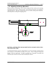
8. Remove side arm tube cover plate (Item #2). Locate pillow block bearings (Item
#12). Do not tighten set screws. Now center assembly with housing. When
assembly is correctly centered, tighten bearing set screws.
9. Insert arm, with endlock intact, into the main arm tube base. Push tube far
enough to make the cable, connections at the pivot. After cables have been
securely bolted to the pivot mechanism, extend arm so that the endlock saddles
satisfactorily over the anchor assembly (on the bollard). Slide lock coller into
place and tighten allen bolts.
NOTE 6: If endlock fails to line up properly, loosen bearing bolts and rotate
laterally. Re-tighten bolts. Now tighten arm base bolts securely.
Replace side arm tube cover plate (tighten bolts securely).
10. With the arm in the down position, install the allotted amount of counterweights
(Item #3) on the side arm tube assembly. Tighten bolts securely.
11. Close the main disconnect switch (S1) and operate the control circuit. If all
connections are made correct, barrier arm will operate to fully up or fully down.
The limit switch will automatically stop the motor at the extreme 90-degree
movement of the arm.
12. With the barrier in the lowered position, check endlock mechanism for any type
of hindrance with bollard post and adjust accordingly if required.
IMPORTANT: IF THREE PHASE POWERE CONNECTIONS TO THE
MOTOR ARE REVERSED, THE LIMIT SWITCH WILL
AUTOMATICALLY DISCONNECT THE MOTOR WHEN THE
DRIVE CRANK HAS ROTATED ABOUT 30 DEGREES IN THE
INCORRECT DIRECTION, DEPENDING ON THE POSITION OF
THE CONTROLS, i.e., UP OR DOWN. DRIVE CRANK MUST
THEN ROTATE BACK TO ORIGINAL (VERTICAL) POSITION
USING HANDCRANK, IN ORDER TO RESET BARRIER.
If this problem occurs, phase must be reversed. The limit switch has
been set at the factory and should NOT REQUIRE ADJUSTMENT.
Arm should be raised or lowered by lengthening or shortening of the
connecting rod not by adjustment of the limit switch cams.