


Installation & Operations Manual
CR-25E Cable Beam Barrier Specifications 20 of 31
© 2007 B&B ARMR WWW.BB-ARMR.COM (800) 367-0387
The main arm shaft will be mounted in heavy duty ball bearings. The main arm shaft will
be not less than 2 inches in diameter. Shaft material will be ASTM A311 Class B high
strength, stressproof steel.
TRANSMISSION
The transmission will be a fully enclosed, all gear, direct drive unit running in an oil bath.
The drive train will not use belts or chains and will be connected to the arm shaft with a
connecting rod having self-aligning ball ends. The connecting rod will be constructed of
ASTM A311 Class B high strength stressproof steel.
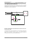
During the opening and closing cycles, the gate arm will begin with zero velocity and
accelerate smoothly reaching maximum velocity at mid-stroke (45 degrees). The arm
will then decelerate smoothly to zero velocity at full stroke (90 degrees) preventing
bounce or whip of the arm. Standard operating time to open or close the gate will be 13
seconds. Consult the factory for other available speeds.
MOTOR
A 110V, 1/2HP Single Phase motor will be supplied. The motor will be of the flange
mounted type, attached to the transmission case with not less than four bolts. The motor
will be of the instant reversing type to permit reversing movement of the arms at any
point of travel. Motor data will appear in the manual.
BRAKING MECHANISM
A solenoid release, automatic motor brake will be furnished as part of the gate drive
mechanism. The brake will automatically release when the handcrank is inserted to
manually operate the gate.
HANDCRANK
A handcrank and drill crank will be included with each gate to operate the gate during
power failure. An automatic safety disconnect switch will automatically break the
control circuit power when the handcrank is inserted to allow for manual operation.
LIMIT SWITCH
The gate limit switch will be a unit assembly containing eight individual switches having
one set of normally open and one set of normally closed contacts each. Contacts will be
totally enclosed and will have U.L. rating of not less than 15 amperes at 220 volts AC.
Limit switch will be readily accessible and easily replaced with normal hand tools. Each
individual switch will be controlled by an independent cam, which will be adjustable with
a hex socket cap screw. The limit switch body, shafts and cams will be of corrosion
resistant non-ferrous materials.