


Installation & Operations Manual
CR-25E Cable Beam Barrier Installation, Adjustment & Maintenance 4 of 31
© 2007 B&B ARMR WWW.BB-ARMR.COM (800) 367-0387
1. INSTALLATION, ADJUSTMENT AND MAINTENANCE
1.1 CR-25E Installation Instructions (Reference Drawing: 0025-0050-A)
NOTE: Failure to install your barrier properly could cause damage to the
operating mechanism.
1. Read the instructions and review the drawings thoroughly. If you do not
understand any part of these instructions, please contact the manufacturer.
2. Check the anchor bolt locations and prepare the foundation for the barrier. Set the
barrier operator and be sure to seal the bottom with duct seal. Housing must be
level. Anchor bolts must be tightened evenly.
3. Make sure the local power supply for the motor and control circuit are correct.
*Reference the enclosed electrical drawing in the back of the handbook.
IMPORTANT: All conduit must be sealed and the housing grounded.
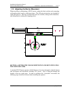
4. Using the hand crank, turn the drive crank 45 degrees noting rotation of the drive
crank should be clockwise.
5. Open main disconnect switch (S1) and connect the power. Connect the control
circuit if separate. If power is supplied from the motor circuit, check the
connections at the terminals.
NOTE: At this point in the installation, no counterweights or arms should
have been installed.
6. "Bump" test barrier operator for correct motor rotation.
NOTE: The drive cranks should rotate upwards toward roadway to raise
barrier arm (viewing barrier operator from either drive crank side of
the housing).
7. Run barrier operator (without arms or counterweights) through several complete
cycles. Leave the barrier operator in the closed to traffic position and open the
main disconnect switch.