


Installation & Operations Manual
CR-25E Cable Beam Barrier Installation, Adjustment & Maintenance 17 of 31
© 2007 B&B ARMR WWW.BB-ARMR.COM (800) 367-0387
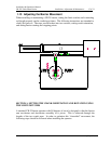
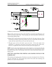
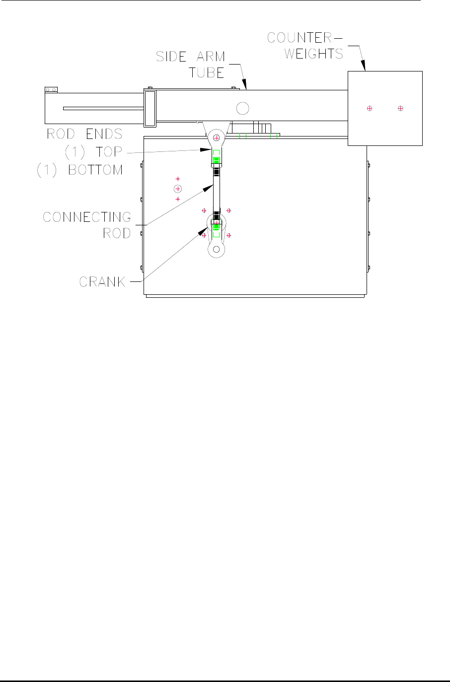
5) Manually rotate the barrier into its fully closed to traffic position.
Note: At fully closed, the lower drive crank should have rotated through 180 degrees, and
should be pointing straight down. The connecting rods should be parallel with the sides
of the housing and the cranks.
6) Rotate Cam 2 until the limit switch follower just falls off of the edge of the cam. Keep
the direction of rotation of the cam in mind as you set it to ensure that when the barrier
rotates, the limit switch follower will move back onto the cam.
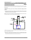
7) Re-apply power and run the barrier open and closed. If the cams require more
adjustment it is important to disconnect power before moving the limit switch cams.
Be sure to re-tighten the limit switch cams once they have been properly set.
NOTE: At this point in the adjustment, the crank orientation is more important than the
barrier position. At the fully open and fully closed positions, the connecting rods should
be parallel with the sides of the housing, and the drive cranks should point directly up or
directly down.
STEP TWO: ADJUSTING THE STOPPING AND STARTING POINTS OF THE
BARRIER ARM
If the starting and stopping points of the barrier arm need to be adjusted, this will be done
using the connecting rods. This should only be done if the cranks and connecting rods
positions are correct as described above.