


Installation & Operations Manual
CR-25E Cable Beam Barrier Installation, Adjustment & Maintenance 16 of 31
© 2007 B&B ARMR WWW.BB-ARMR.COM (800) 367-0387
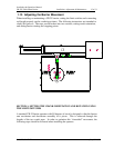
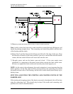
1) Determine the direction of rotation of the cranks. In a standard installation, the cranks
pivot toward the motor, and the roadway.
The limit switch cams rotate the same direction that the pivot rotates. Cam 1 is always
the raise stop, Cam 2 is always the lower stop, Cam 3 generally controls the arm lights if
there are any.
IMPORTANT: Always power down at the main switch before adjusting the limit
switches.
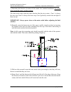
2) Manually rotate the barrier into its fully open to traffic (raised) position by inserting
the manual crank onto the shaft extending from the top of the motor and turning it
until the barrier reaches the desired position.
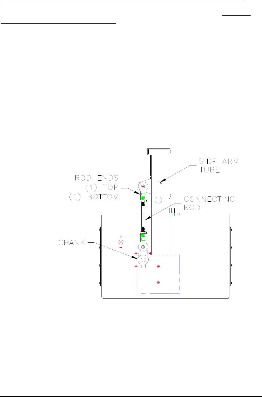
Note: At fully open, the connecting rods should be parallel with the sides of the operator
and with the cranks. The cranks should be pointing straight up.
3) With an allen wrench loosen the limit switch cams just enough so that they will turn,
but not so much that they are loose.
4) Rotate Cam 1 until the limit switch follower just falls off of the edge of the cam. Keep
the direction of rotation of the cam in mind as you set it to ensure that when the barrier
rotates, the limit switch follower will move back onto the cam.