


Installation & Operations Manual
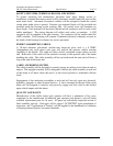
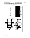
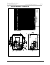
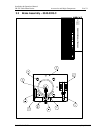
CR-25E Cable Beam Barrier Specifications 21 of 31
© 2007 B&B ARMR WWW.BB-ARMR.COM (800) 367-0387
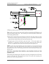
SAFETY SWITCHES, TERMINAL BLOCKS AND WIRING
To protect operating and maintenance personnel from injury during service or
installation, a manual disconnect switch will be furnished, installed and fully wired in the
main motor leads. Automatic disconnect switches will be arranged to break the control
circuit when either door is opened. Pressure type terminal blocks will be provided and
installed inside the housing on the roadway side. All control wires will terminate on
these blocks. Each terminal will be clearly labeled and all conductors will be color coded
and/or numbered. The wiring diagram will reflect such colors or numbers. A GFI
receptacle will be supplied in the gate housing. No conductor will be smaller than #16
AWG stranded. Each housing will contain a laminated electrical schematic secured to
the inside of the housing for reference by service personnel.
ENERGY ABSORPTION CABLES
A 7/8-inch diameter galvanized, double-extra improved plow steel 6 x 9 IWRC
(independent wire rope center) wire rope will provide the primary vehicle restraint
capability of the barrier. The cable will have closed, cad-plated swage sockets on each
end. Both ends of the cable will be anchored securely at the operator end of the beam
doubling the cable. The cable assembly will be enclosed inside the arm and will form a
loop at the end of the beam arm.
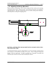
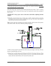
CABLE ANCHORING SYSTEM
The cable assembly will be designed to securely engage an anchor post at the arm end on
impact. The engaged assembly will be designed to anchor the cable assembly at each end
of the beam at all times when the arm is in the closed position to withstand collision
loads.
Engagement of the anchoring assemblies at each end will not rely upon any electrical,
hydraulic, magnetic or other powered devices. A clevis mounted on the end of the crash
beam will be designed to securely and passively engage and lock itself to the bollard
upon vehicle impact with the beam.
QUALITY ASSURANCE
Manufacturer of the traffic control gate operator will have a minimum of five years
experience in the manufacture of industrial gate operators and barriers, and will make
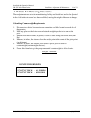
available replacement parts for 10 years. All gates are individually inspected at time of
final assembly and test. Each gate will be tagged "ACCEPTED" upon completion of
inspection and “Certification of Testing” will be supplied in the handbook for validation
of meeting internal Quality Assurance standards.