


Installation & Operations Manual
CR-25E Cable Beam Barrier Installation, Adjustment & Maintenance 14 of 31
© 2007 B&B ARMR WWW.BB-ARMR.COM (800) 367-0387
1.12 Gate Arm Balancing Instructions
These adjustments are set at the manufacturing facility and should not need to be adjusted
in the field unless the arms have been modified, causing the weight of the arm to change.
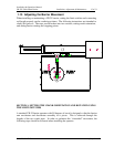
Calculating Counterweight Requirements
1. Disconnect arm drive by removing top connecting rod bolts located on each side of
the operator.
2. Mark any place on the barrier arm and attach a weighing scale to the arm at that
point.
3. Measure how much weight, in pounds, it takes to start raising the barrier arm. (arm
lbs.)
4. Measure, in inches, the distance from the weight point to the center of the pivot point
(arm distance).
5. Measure, in inches, the distance from center of pivot point to center of
counterweight (counterweight distance).
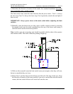
6. Follow this formula to get the proper amount of counterweight to add to barrier.
arm lbs. x arm dist.
cw dist.
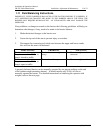
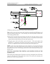
COUNTERWEIGHT SIZES
12”X12”X1” THICK = 41 POUNDS
12”X12”X2” THICK = 82 POUNDS