


Installation & Operations Manual
CR-25E Cable Beam Barrier Installation, Adjustment & Maintenance 15 of 31
© 2007 B&B ARMR WWW.BB-ARMR.COM (800) 367-0387
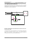
1.13 Adjusting the Barrier Movement
When installing or maintaining a CR-25 barrier, setting the limit switches and connecting
rod length properly can be confusing at times. The following instructions are intended to
clarify this process. The steps can be broken into two sections, setting crank orientation,
and setting barrier starting and stopping points.
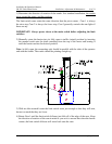
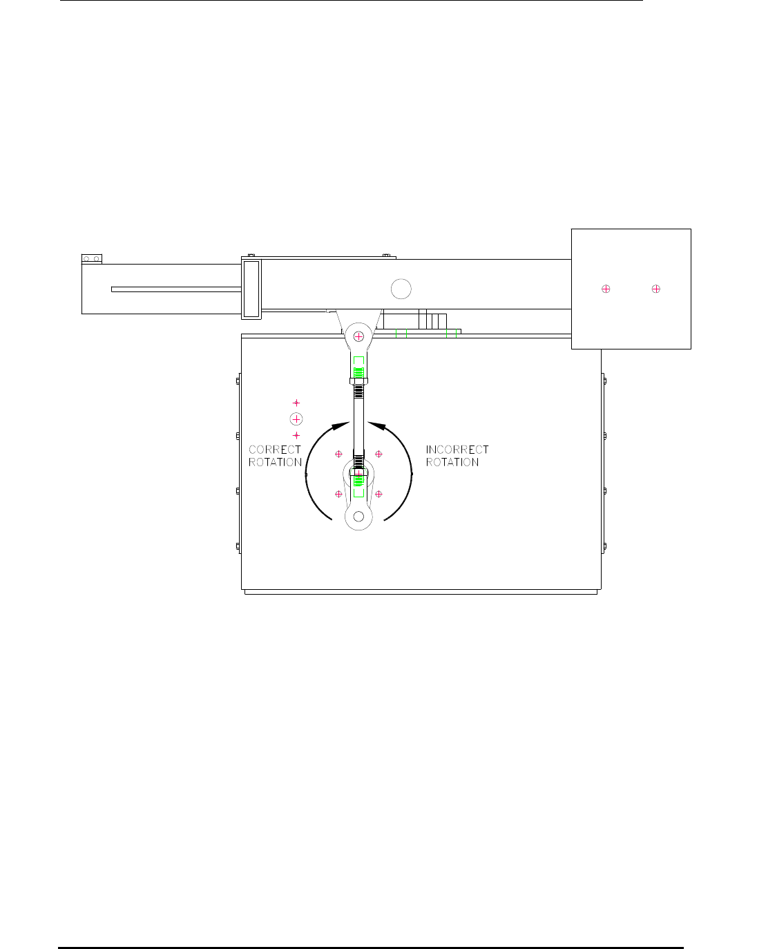
SECTION 1: SETTING THE CRANK ORIENTATION AND ROTATION USING
THE LIMIT SWITCHES
A standard CR-25 barrier operator with 90 degrees of travel is designed so that the barrier
arm accelerates and decelerates smoothly as it pivots. This is achieved through the
lengths of the two crank arms. In order to optimize this “sinusoidal” movement, the
following steps should be followed when installing the operator.