


MSWU-81E 29/09/2014
43
8.Image
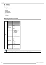
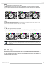
8.7 Input Balance
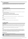
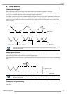
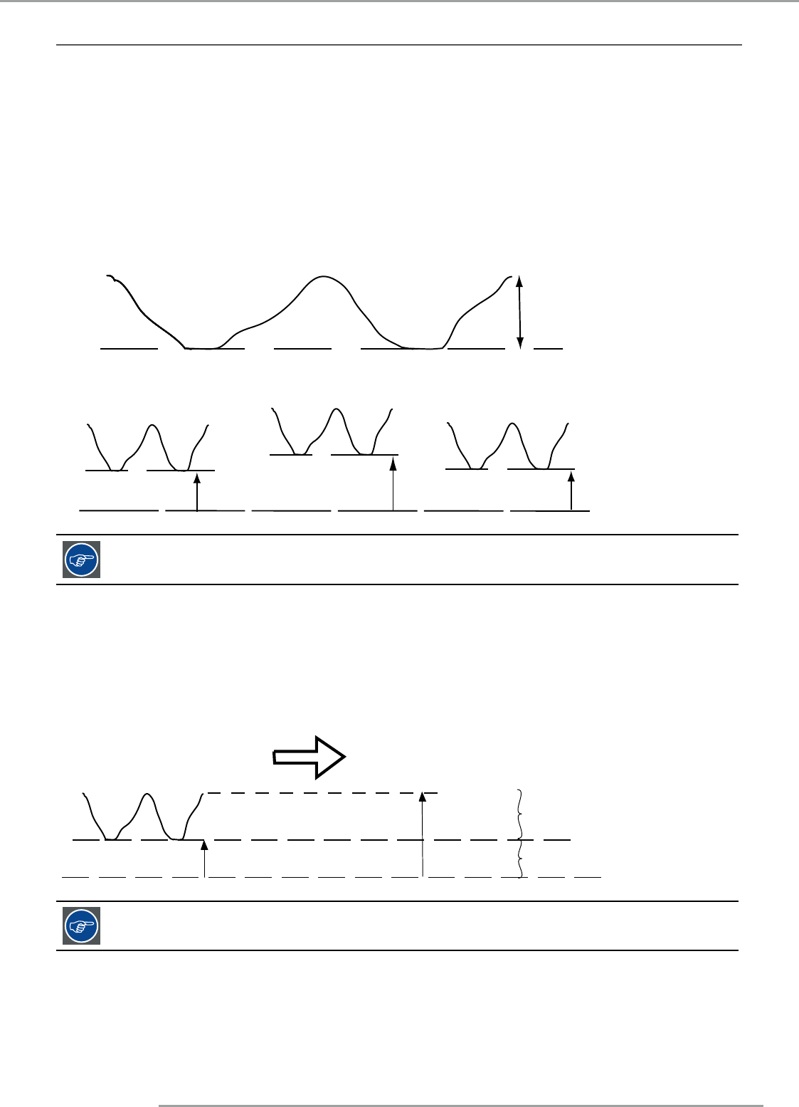
Unbalanced color signals
When transporting signals, there is always a risk of deterioration of the information contained in the signals.
In case of information contained in the amplitude of the signals which is the case of data color signals (R, G, B),image 9-29 ,
we are quite sure that the amplitude of these color signals is subject to alterations.
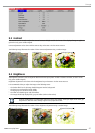
An example of alteration may be a DC component added to the signal, in the form of a DC offset repositioning the black level,
since this black level (“brightness”) will become crucial later on (clamping circuit) it will result in “black not being black”.
Another value that is subject to alteration is the amplitude of the signal, resulting in an altered “Gain” of the signal (“white
level” or contrast).
The alterations of the three color signals will happen independently i.e. the colors will end to be unbalanced, image 9-30
B
Black level
0.7V
Image 9-29
Black level
∆
G
∆Β
∆
R
R
G
B
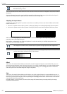
One can conclude here that a good color tracking can only be met by using three previously (input)
balanced color signals
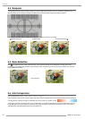
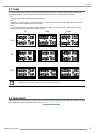
Analog Digital Conversion
The analog color signals must pass through an Analog/Digital conversion circuit prior to any digital processing in the PMP. A
typical ADC transforms the analog value into an 8 bit coded digital signal.
The graphic shows that when converting a signal containing a DC offset component the range of the converter is not optimally
used.
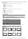
Black level
∆
R
ADC
0
255
i1 : superfluous information
i2 : video information
One can conclude here that a good data conversion can only be met by using three previously (input)
balanced color signals
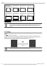
The objective of input balancing
The objective in input balancing is to “set” the same black level and the same white level for the three colors of a particular
input source.