


66-EN
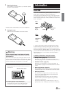
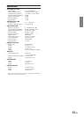
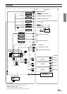
1 Antenna Receptacle
2 Power Antenna Lead (Blue)
Connect this lead to the +B terminal of your power antenna,
if applicable.
• This lead should be used only for controlling the vehicle's power
antenna. Do not use this lead to turn on an amplifier, or a signal
processor, etc.
3 Remote Turn-On Lead (Blue/White)
Connect this lead to the remote turn-on lead of your
amplifier or signal processor.
4 Audio Interrupt In Lead (Pink)
5 Illumination Lead (Orange)
This lead may be connected to the vehicle's instrument
cluster illumination lead. This will allow the backlighting of
the unit to dim whenever the vehicle's lights are turned on.
6 Switched Power Lead (Ignition) (Red)
Connect this lead to an open terminal on the vehicle's fuse
box or another unused power source which provides (+)12V
only when the ignition is turned on or in the accessory
position.
7 Battery Lead (Yellow)
Connect this lead to the positive (+) post of the vehicle's
battery.
8 Fuse Holder (7.5A)
9 Ground Lead (Black)
Connect this lead to a good chassis ground on the vehicle.
Make sure the connection is made to bare metal and is
securely fastened using the sheet metal screw provided.
! Monitor Control Lead (Front) (White/Pink)
Connect this to the Monitor Control Lead of the touch panel
compatible front monitor.
" Monitor Control Lead (Rear) (White/Pink)
Connect this to the Monitor Control Lead of the touch panel
compatible rear monitor.
# Remote Control Input Lead (Touch panel compatible
front monitor) (White/Brown)
Connect this to the remote control output lead for the touch
panel compatible front monitor.
$ Remote Control Input Lead (Rear) (White/Brown)
Connect this to the remote control output lead for the rear
monitor.
• If the optional remote control eye (KRE-500E) is connected, the
remote control signal cannot be received.
% Amplifier Link Connector
Outputs Amplifier Link control signals.
Connect this to an external Amplifier Link compatible
& Video Output Connector (Yellow)
Output the video
( Audio Output Connectors
RED is right and WHITE is left output the audio.
) Front Output RCA Connectors
RED is right and WHITE is left.
~ Rear Output RCA Connectors
RED is right and WHITE is left.
+ Subwoofer RCA Connectors
RED is right and WHITE is left.
, S Video output terminal
Outputs the video signal.
Connect a monitor that has a S video input terminal.
- Digital Output Terminal (Optical)
Use when combining fiber digital input compatible products.
. Remote Control Eye Jack
If a monitor other than Alpine is installed, it can still be
controlled by the supplied remote control by installing the
optional remote control eye (KRE-500E).
/ Steering Remote Control Interface Connector
To steering remote control interface box.
: Power Supply Connector
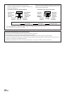
; Setting the 3WAY/2WAY switch
Set the 3way/2way switch according to your audio system.
< RCA Extension Cable (sold separately)
= Ai-NET Connector
Connect this to the output or input connector of another
device (CD Changer, Equalizer, INTERFACE ADAPTER
FOR iPod™* etc.) equipped with Ai-NET.
* When connecting iPod, INTERFACE ADAPTER FOR iPod™
(KCA-420i) is required. For details on how to connect, refer to
the Owner's Manual of KCA-420i.
•You can input TV/video sound by connecting an optional
Ai-NET/RCA Interface cable (KCA-121B) to this component.
> Ai-NET Cable (Included with CD Changer)
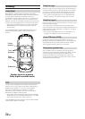
? Power Supply Box
• Do not install the Power Supply Box at a location subjected to
water such as under the floor mat or air conditioner. This may
cause a malfunction.
• Do not bundle the Power Supply Box cable with other audio
cables. Doing so may induce noise into your system.
•Keep the Power Supply Box converter away from the Antenna
cables and the rear side of the unit, otherwise noise may be
generated when receiving radio broadcast.
amplifier, using the (also separately sold) Amplifier Link
box KCE-511M.